© 2014 MIMAKI ENGINEERING CO.,LTD. 4.1.5 P.1
1
2
3
4
R.1.0
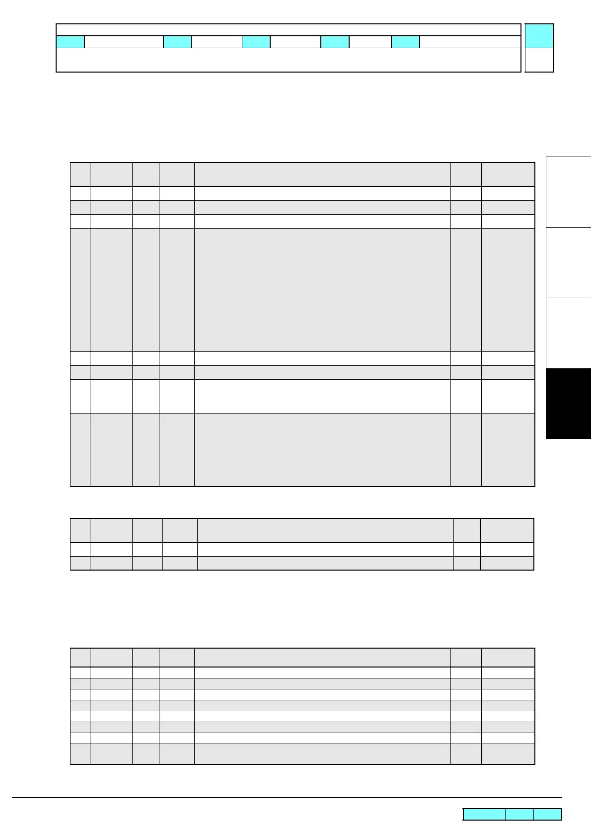
4.1.5 Important Parameter
Outline
This section shows the parameters necessary in repair and verification work.
Important parameters
SYSTEM PARAMETER
INK PARAMETER1
HEAD PARAMETER
Drop position adjusting value has been saved.
For details, refer to the parameter list.
CUT SYSTEM PARAMETER
No. Display
Initial
Val ue
Adjusted
Val ue
Description Unit Input Range
007 FLSposY 0 Flushing Y position adjustment 0.1mm -200~200
008 CapPosY 0 Capping Y position adjustment 0.1mm -200~200
009 WipPosY 0 Wiping Y position adjustment 0.1mm -200~200
032 INK SET 0
Ink set
0 :MMCCYYKK :SS21
0 :MMCCYYKK :BS3
2:MWCWYLmKLc :SS21
4 :MMBBYYKK :Sb53
6:MMBBYLmKLb :Sb53
7:MSiCWYLmKLc :SS21
8:MOrCLkYLmKLc :SS21
M;Magenta, C;Cyan, Y;Yellow, K;Balck, W;White,
Lm;Light magenta, Lc;Light cyan, B;Blue, Lb;Light blue,
Si;Silver, Or;Orange, Lk;Light black
codes
0x0000
~0x00ff
109 AirVacY 0 Air vacuum Y position adjustment Pulses -200~ 200
124 MECASIZ 6 Mecha size 6: 130, 7: 160 codes 0~10
129 SUPPORT 0
Adjustment functionality expansion
2: Adjustment functionality expansion
3: Adjustment functionality expansion + English
codes 0~2
130 INITIAL 0
Initialization 1: All parameters (1: 2 head machine, 2: 1 head machine)
10: Restore from FROM to EEPROM (Not used)
11~:Parameter initialized at update
(11: 2 head machine, 12: 1 head machine)
20: Reserve
21~:System parameter and Operation parameter
(21: 2 head machine, 22: 1 head machine)
codes 0~255
No. Display
Initial
Val ue
Adjusted
Va lu e
Description Unit Input Range
000 INKSET 0x0000 Initial filling performing flag: Bit allocation ^0=Head 1 ~ ^7=8 0~255
256 SubsSW 1
Filling fluid filling (for initial filling) execution flag
1=Execute
0~1
No. Display
Initial
Va lu e
Adjusted
Va lu e
Description Unit Input Range
2 ANGLE 0 Right-angle compensation value -40 to 40
21 PTRofxX 0 Pointer offset X [in units of 0.1 mm] 0.1mm -100 to 100
22 PTRofsY 0 Pointer offset Y [in units of 0.1 mm] 0.1mm -100 to 100
24 SENS.A 0 Photo sensor position adjustment X 0.1mm -100 to 100
25 SENS.B 0 Photo sensor position adjustment Y 0.1mm -100 to 100
26 P>COTSX 0 Print head cut head origin position adjustment X 0.1mm -100 to 100
27 P>COTSY 0 Print head cut head origin position adjustment Y 0.1mm -100 to 100
30 CUT.OVL 1000
Cutting overrun distance (Left)
(Cut offset from the leftmost pinch roller)
0.1mm -1000 to 2000
Service Documents > Technical Information > Basic Information > Important Parameter
Model
CJV150/300
Issued
2014.09.15
Revised F/W ver
1.10
Remark
1.0
 Loading...