Do you have a question about the Minarik PCM21000A and is the answer not in the manual?
Important safety tips, warnings, and procedures for equipment installation and operation.
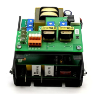
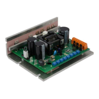
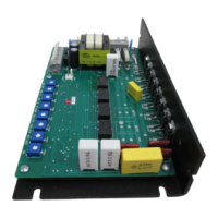
Procedures and considerations for physically mounting the drive unit.
Guidelines and requirements for connecting the drive's electrical wiring.
Recommendations for shielding power and logic leads to prevent interference.
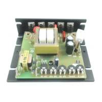
Requirements for applying additional heat sinks for specific operating conditions.
Information on selecting and installing external fuses for drive protection.
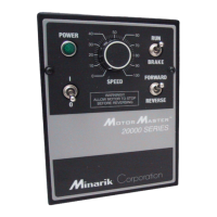
Instructions for mounting and wiring the speed adjust potentiometer.
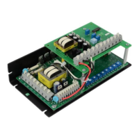
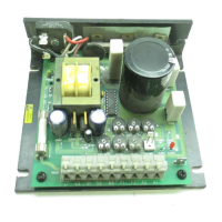
Overview of power, fuse, and motor connections for the drive.
Details on connecting the AC line power and recommended master switch.
Wiring instructions for using a voltage signal to control the PCM2x000A drive.
Wiring instructions for using a voltage signal to control the PCM2x000C drive.
Wiring instructions for using a current signal to control the PCM2x000C drive.
Checks and preparations required before powering up the drive.
Step-by-step guide for starting the motor and adjusting speed.
Recommended methods for starting and stopping the motor safely.
Using the RUN/STOP switch to decelerate the motor to a halt.
General steps and order for calibrating drive settings.
How to set the speed based on the input voltage or current signal.
Procedure to set the lowest possible motor speed.
Procedure to set the highest possible motor speed.
Calibrating the maximum armature current output for motor protection.
Adjusting speed consistency under varying load conditions.
Configuring the drive for two distinct speed settings using switches.
Setting up multiple predefined motor speeds using resistors and switches.
Using multiple potentiometers in series for adjustable speed selection.
Connecting and using a RUN/JOG switch for motor operation control.
Initial checks and contact information for support.
Explains the meaning of the POWER, SIGNAL, and CURR LIM LEDs.
Steps to diagnose why the motor fails to start or operate.
Troubleshooting common issues related to blown fuses or tripped breakers.
Addresses issues where the motor fails to stop when set to minimum speed.
How to correct motor operation in the reverse direction.
Diagnosing and fixing speed reduction under load.
Resolving issues with fluctuating motor speed during operation.
Troubleshooting why the motor operates at maximum speed constantly.
Defines the roles and responsibilities of users and OEMs regarding compliance.
Details on EMI/RFI safeguards and required external filtering.
Terms and conditions of the product's warranty coverage.
Limitations and exclusions of the warranty and liabilities.
Specifies the extent of the corporation's liability for damages.
| Input Voltage | 115/230 VAC |
|---|---|
| Output Current | 10 A |
| Horsepower | 1 HP |
| Speed Range | 50:1 |
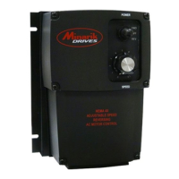
| Enclosure Type | NEMA 1 |
| Output Voltage | 0-90/0-180 VDC |