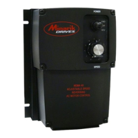
Variable Frequency Drive for
3-phase & single phase AC motors
QUICK START GUIDE
VFDP4X04-D230-PCM
DIMENSIONS
SPECIFICATIONS
1-Phase Input . . . . . . . . . . . . . . . . . . . . . . . . . . . . . . . . . . . . . . . . . . . .* 115/230 VAC
1 or 3 -Phase Output . . . . . . . . . . . . . . . . . . . . . . . . . . . . . . . . . . . . . . . . . . .230 VAC
Maximum Horsepower . . . . . . . . . . . . . . . . . . . . . . . . . . . . . . . . . . . . . . . . . . . . .1 HP
Maximum Continuous Output Current . . . . . . . . . . . . . . . . . . . . . . . . . . . . . . . 4.0 AC
AC Amps In . . . . . . . . . . . . . . . . . . . . . . . . . . . . . . . . . . . . . . . . . . . . . .15 / 10 amps
AC Voltage Input Range . . . . . . . . . . . . . .115/230 VAC ± 10%, 50/60 Hz single phase
Standard Carrier Frequency . . . . . . . . . . . . . . . . . . . . . . . . . . . . . . . . . . . . . . .16 KHz
Adjustable Braking Current . . . . . . . . . . . . . . . . . . . . . . . . . . . . . . . . . . . . . .0 - 4 ADC
Adjustable Braking Time . . . . . . . . . . . . . . . . . . . . . . . . . . . . . . . . . . . . . . .1 - 10 Sec.
Adjustable Minimum Speed . . . . . . . . . . . . . . . . . . . . . . . . . . . . . . . . . . . . . .0 - 30 Hz
Output Frequency Range . . . . . . . . . . . . . . . . . . . . . . . . . . . . . . . . . . . . . .0 - 120 Hz
Adjustable Maximum Output Frequency Range . . . . . . . . . . . . . . . . . . . . .30 - 120 Hz
Acceleration Time Range . . . . . . . . . . . . . . . . . . . . . . . . . . . . . . . . . . . . . .1 - 12 secs
Deceleration Time Range . . . . . . . . . . . . . . . . . . . . . . . . . . . . . . . . . . . . . .1 - 12 secs
Analog Input Voltage Range (S1 [-] to S2 [+]) . . . . . 0 - 5 VDC, 0 - 10 VDC, 4 - 20 mA
Input Impedance, S1 to S2 . . . . . . . . . . . . . . . . . . . . . . . . . . . . . . . . . . .~ 100K ohms
Vibration . . . . . . . . . . . . . . . . . . . . . . . . . . . . . . . . . . . . . . . . . .0.5G max (20 - 50 Hz)
0.1G max (> 50 Hz)
Weight . . . . . . . . . . . . . . . . . . . . . . . . . . . . . . . . . . . . . . . . . . . . . . . . . . . . . . .1.2 lbs
Ambient Operating Temperature Range . . . . . . . . . . . . . . . . . . . . . . . . . . .10° - 40° C
* Jumper settings MUST
match input line voltage.
Application of 230 VAC
line input when jumpers
are set for 115 VAC will
result in severe damage
to the drive.
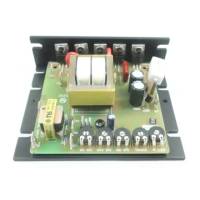
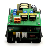
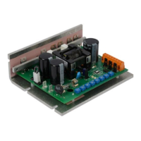
1. Remove the six (6) phillips screws on the
front case.
NOTE: The two shorter screws (#6 - 32 x 2
1/2) on the front case are used at hole
locations 5 & 6.
2. Remove the five (5) phillips screws on the
bottom plate.
NOTE: DO NOT REMOVE the three (3)
screws securing the bottom plate to the
heatsink.