Passport 5-Lead, 5L, LT, XG Service Manual 0070-00-0420 2 - 59
Theory of Operation Block Diagrams
2.2.9 NIBP Module: NIBP Pneumatic Board
0670-00-0447-XX, 0670-00-0605-xx (Linear Bleed) and Control
Board 0670-00-0375
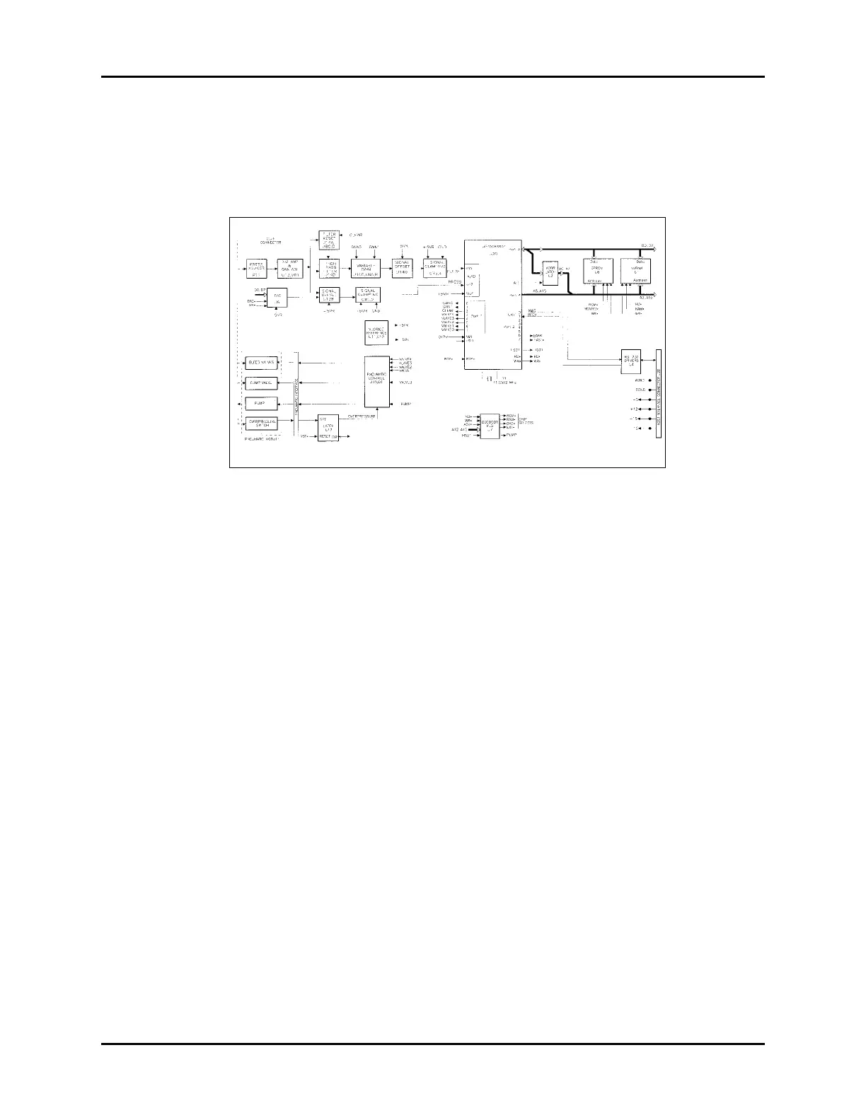
FIGURE 2-26 NIBP Module Block Diagram
Overview
The NIBP module consists of two boards interconnected by a 20 pin cable: the control board
that contains most of the electronic circuitry ; and a pneumatic board that contains all the
pneumatic parts.
The CPU
The electronics are built around a 16 bit microcontroller (80C196). Built into the 80C196, in
an 8-channel 10-bit A/D converter, five 8-bit I/O ports, pulse width modulators, high-speed
inputs and outputs, an UART, a watchdog timer, and two 16-bit counter/timer.
An 11.0592MHz crystal is connected to the on-chip oscillator of the 80C196. This
frequency is chosen for accurate generation of standard baud rates (the on-chip UART has an
integral baud rate generator). An RC circuit, R1 and C1, resets the 80C196 on power-up.
The microcontroller can also be reset from an external, open-collector, active low reset signal
from Pin 8 of connecter J28.
The non-maskable interrupt, NMI, of the 80C196 is used to detect the overpressure (OVPR)
condition. A low to high transition on the OVPR signal will cause the microcontroller to sense
the overpressure condition. The OVPR signal is also connected to the high speed input bit 1
of the microcontroller for it to verify the overpressure condition.
The BUSWIDTH input is tied low since the eight bit data bus mode is used for external
memory access. The EA/ pin is tied low since external EPROM and static RAM are used for
program and data memory.