EasyManua.ls Logo

Mindray Passport 12 - Service Manual

Mindray Passport 12
106 pages
Print Icon
To Next Page IconTo Next Page
Loading...
Passport 12/Passport 8
Patient Monitor
Service Manual

Table of Contents

Other manuals for Mindray Passport 12

Questions and Answers

  • G
    Gwendolyn SkinnerSep 22, 2025
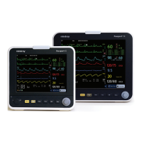
    What causes baseline wander on Mindray Passport 12 Medical Equipment and how to fix it?
    • B
      Barbara FriedmanSep 22, 2025
      If you observe baseline wander on your Mindray Medical Equipment, it could be due to several reasons. First, if the patient is moving excessively, try to secure the lead wires and cable to the patient. Second, check if the electrodes are dry or loose; if so, repeat skin preparation and apply fresh and moist electrodes. Lastly, ensure that the ECG filter is set to 'Monitor' mode, as setting it to 'ST' or 'Diagnostic' mode can also cause baseline wander.
  • Y
    yelliottAug 25, 2025
    What to do if the touchscreen on my Mindray Passport 12 Medical Equipment monitor does not respond?
    • W
      William ComptonAug 25, 2025
      If the touchscreen on your Mindray Medical Equipment does not respond, first check if the touchscreen is disabled. Look for a symbol above the [Main Menu] quickkey; if present, press and hold the [Main Menu] quickkey for more than 3 seconds to enable it. If that doesn't work, check the cables between the touchscreen and touchscreen control board, and between the touchscreen control board and main board to ensure they are correctly connected. If the problem continues, the touchscreen control board, the touchscreen itself, or the main board might be defective and require replacement.
  • T
    Tyler HillAug 25, 2025
    Why is the display blank on my Mindray Passport 12 monitor?
    • M
      Morgan MckenzieAug 26, 2025
      If your Mindray Medical Equipment display is blank or black, the issue might stem from a defective cable, main board, or the display itself. Start by checking if the cable between the display and main board, including the backlight cable, are correctly connected and undamaged. If the connections are secure, the main board or the display could be defective and might need replacement.
  • W
    Willie JonesAug 27, 2025
    How to troubleshoot no alarm sound on Mindray Passport 12?
    • S
      Sarah PerryAug 27, 2025
      If you are experiencing no alarm sound or abnormal alarm sounds on your Mindray Medical Equipment, it could be due to the alarm sound being set to zero. To resolve this, select [Main Menu]?[Maintenance >>]?[User Maintenance >>]?enter the required password ?[Alarm Setup >>] and set the [Minimum Alarm Volume] to an appropriate level. You can also adjust the alarm volume by selecting [Alarm Setup] on the main menu. Also, check that the cable between the speaker and interface board is properly connected. If the problem persists, the speaker, main board, or power management board may be defective and require replacement.
  • R
    robertwilliamsSep 23, 2025
    Why is there no ECG waveform on my Mindray Passport 12?
    • B
      Bianca JonesSep 23, 2025
      If there is no ECG waveform on your Mindray Medical Equipment, first ensure that the gain is appropriately set. If the gain is too low, you won't see a waveform. Next, check that the lead wires and patient cable are fully and properly inserted. Finally, inspect the cables and lead wires for any damage, and replace them if necessary.
  • J
    Jason ScottDec 1, 2025
    Why can't my Mindray Medical Equipment connect to Wi-Fi?
    • T
      taylorstaceyDec 1, 2025
      If your Mindray Medical Equipment is unable to connect to the Wi-Fi network, it may be due to an unstable Wi-Fi signal. Verify that the network is available and that the network type is correctly set (e.g., LAN or WLAN). Also, check that the SSID and password of the monitor match those of the wireless AP. Ensure there are no IP address conflicts and that the IP addresses are correctly set. It is also recommended to use a Mindray recommended wireless AP, ensuring it meets the throughput requirements. Verify the AP channel bandwidth is 20 MHz, and that the wireless AP signal strength is no less than -65 dBm where the monitor is located. Check that the signal strength of other Wi-Fi devices at the same channel is no greater than -85 dBm, and that the signal strength of other Wi-Fi devices of ...
  • C
    Christopher AllenSep 12, 2025
    Why can't I connect external modules to my Mindray Passport 12?
    • K
      Kelly TurnerSep 12, 2025
      If you are experiencing issues with connecting external parameter modules to your Mindray Medical Equipment, it could be due to a module defect or a main unit defect. Check that the cable between the external converter board inside the module and the converter board is correctly connected, and consider replacing the converter board. Also, verify that the cable between the main board and power management board is correctly connected, and consider replacing the power management board or the main board.
  • B
    Benjamin BrooksSep 12, 2025
    What to do if Mindray Medical Equipment fails to review data?
    • S
      Sarah RandallSep 12, 2025
      If your Mindray Medical Equipment fails to review archived patient data, it might be due to abnormal patient admitting. Ensure the patient is admitted properly. It could also be due to the SD card being full. Delete unnecessary patient data and remove related alarms, then readmit the patient. If the issue persists, the main board might be defective and need replacement.
  • J
    Jason MeyerSep 4, 2025
    Why is the secondary display not working on my Mindray Passport 12?
    • A
      Andrew RoblesSep 4, 2025
      If the secondary display on your Mindray Medical Equipment does not function or displays snow or flashing specks, it could be caused by a defective cable or the connector board. Check that the cable between the secondary display and the monitor, the cable between the main board and power management board, and the cable between the power management board and interface board are correctly connected. If the connections are correct, the connector board might be defective and need replacement.
  • J
    Janet CooleySep 2, 2025
    How to resolve poor print quality on Mindray Medical Equipment?
    • L
      Lauren BrownSep 2, 2025
      If you are experiencing poor print quality or paper not feeding properly on your Mindray Medical Equipment, it might be due to the paper roll not being properly installed. Stop the recorder and re-install the paper roll. Also, check the thermal print head and the paper roller for any foreign matter and clean the thermal print head with an appropriate clean solution. If the issue persists, the recorder itself may be defective and need replacement.

Summary

Safety

1.1 Safety Information

Provides crucial safety information, including warnings and cautions for proper operation.

1.1.1 Warnings and Cautions

Details critical warnings and cautions regarding electrical hazards, handling, and environmental factors.

1.2 Equipment Symbols

Explains various symbols used on the equipment and in the manual for clear identification.

Theory of Operation

2.1 The Basics

Overview of the patient monitor's design, functions, and basic operational principles.

2.2 System Connections

Describes how the monitor connects to peripheral devices and installation support options.

2.2.2 Peripheral Device Connectors

Details the connectors on the rear of the monitor for peripheral device attachment.

2.3 Main Unit Architecture

Illustrates the main unit's internal architecture, including front and rear housing components.

2.4 Front Housing Assembly Components

Details components within the front housing: main board, keypad, alarm lamp, Wi-Fi module.

2.5 Rear Housing Assembly Components

Details components within the rear housing: power boards, interface boards, recorder, etc.

2.5.1-2.5.6 Board Descriptions

Provides descriptions for AC/DC Power Board, Power Management Board, Interface Board, etc.

2.5.7-2.6.1 Module Components

Details SpO2 Board, Parameter Connector Board, and Module Converter functions.

2.6.2-2.6.5 Module Types

Describes Converter, IBP+C.O., CO2, and AG modules and their functions.

Unpacking and Installation

3.1 Unpacking the Equipment

Instructions for opening packages, checking contents against the packing list, and handling damage.

3.2 Preparation for Installation Site

Ensures site meets safety, environmental, and power requirements. Details environmental specifications.

3.2.2 Electrical Requirements

Specifies electrical requirements, including line voltage, current, frequency, and grounding.

3.2.5 Wireless Network Specification

Details network standards, modulation, operating frequency, QoS, channel spacing, and baud rate.

3.2.7 Network Type & 3.2.8 Wireless Network Setup

Guides setting network type (LAN/WLAN) and configuring wireless network parameters like SSID and security.

3.2.9 WLAN Channels & 3.2.10 Certificates Maintenance

Covers setting WLAN band/channels and managing security certificates for network access.

3.2.11 QoS & 3.2.12 Multicast Parameters

Configures Quality of Service (QoS) for network transactions and multicast parameters.

Hardware and Software Upgrade

4.1 Hardware Upgrade Options

Lists supported hardware upgrades for functions like IBP, CO2, AG, Wi-Fi, and recorder.

4.1.2 Hardware Upgrade Methods

Details methods for upgrading parameter modules, wireless function, and installing hooks.

4.2 Software Upgrade

Provides information and contact for performing software upgrades by authorized personnel.

Testing and Maintenance

5.1 Introduction & 5.2 Preventative Maintenance

Introduces testing procedures and preventative maintenance actions to ensure normal function.

5.2.2 CO2 Tests and Calibration

Covers CO2 module leakage test, accuracy test, and calibration procedures.

5.2.2.3 CO2 Calibration

Step-by-step guide for performing CO2 module calibration using gas cylinders.

5.2.3 AG Tests and Calibration

Details AG module leakage test, accuracy test, and calibration procedures with standard gases.

5.2.3.3 AG Calibration

Procedure for performing AG module calibration, including pressure and gas concentration checks.

5.3 Performance Tests

Outlines recommended frequencies for performance tests and guidelines for visual inspection.

5.3.3 ECG Tests & 5.3.4 Resp Performance Test

Covers ECG performance testing, verification, and respiration performance testing procedures.

5.3.5 SpO2 Test & 5.3.6 NIBP Leakage Test

Details SpO2 testing and NIBP leakage testing procedures, including required tools.

5.3.6.2 NIBP Accuracy Test

Step-by-step guide for performing NIBP accuracy tests using manometer and rigid vessel.

5.3.7 Temp Test & 5.3.8 IBP Performance Test

Covers temperature sensor testing and invasive blood pressure performance testing.

5.3.9 C.O. Test & 5.3.10 Nurse Call Reply Performance Test

Details Cardiac Output (C.O.) testing and Nurse Call Reply performance testing procedures.

5.4 Electrical Safety and Other Tests

Covers electrical safety tests and the power-on self-test procedure for the monitor.

5.4.4 Touchscreen Calibration & 5.4.5 Recorder Check

Procedures for touchscreen calibration and checking the recorder's functionality.

5.4.6 Battery Checks & 5.4.7 Network Print Test

Details battery function/performance tests and network printer connectivity test.

5.5 Factory Maintenance Operations

Guides accessing factory maintenance, configuring central station, and checking software/monitor info.

Troubleshooting

6.1 Introduction & 6.2 Part Replacement

Introduces troubleshooting steps and guidelines for replacing defective PCBs or parts.

6.6.1 Power On;Off Failure & 6.6.2 Display Failures

Troubleshooting common power issues and display problems like blank screens or distorted images.

6.6.3 Alarm Lamp Failures & 6.6.4 Button and Knob Failures

Addresses issues with alarm lamps, unresponsive buttons, or malfunctioning knobs.

6.6.5 Sound Failures & 6.6.6 Battery Failures

Troubleshoots sound issues (alarms, keys) and battery charging or performance problems.

6.6.7 Recorder Failures & 6.6.8 Output Interface Failure

Covers recorder issues (no printout, poor quality) and output interface problems (analog, USB).

6.6.9 Data Storage Failure & 6.6.10 Wired Network Related Problems

Troubleshoots data storage failures (SD card) and wired network connectivity issues.

6.6.11 Wi-Fi Related Problems

Addresses common Wi-Fi issues such as disconnection, instability, and slow transmission.

6.6.12 Module Failures

Troubleshoots problems related to external parameter module connection and communication.

Disassembly and Repair

7.1 Tools Required & 7.2 Preparations for Disassembly

Lists required tools and essential preparation steps before disassembling the equipment.

7.3 Disassembling the Main Unit

Step-by-step guide to separating the main unit's front and rear halves.

7.3.2-7.3.4 Module & Board Removal

Details disassembly of parameter modules, connector panels, and SpO2/Parameter boards.

7.3.5 Pump and Valve & 7.3.6 Recorder Removal

Provides instructions for removing the pump, valve assembly, and the optional recorder.

7.3.7 Battery Interface & Power Board (Passport 8)

Instructions for removing battery interface and power boards specifically for Passport 8.

7.3.8 Battery Interface & Power Board (Passport 12)

Instructions for removing battery interface and power boards specifically for Passport 12.

7.3.9 Power Management Board Removal

Procedure for disconnecting and removing the power management board.

7.3.10-7.3.11 Interface Board Removal

Instructions for removing the interface board for both Passport 8 and Passport 12.

7.4.1 Touchscreen Control Board & 7.4.2 Wi-Fi Module Removal

Details removing the touchscreen control board and the Wi-Fi module.

7.4.3 SD Card & 7.4.4 Main Control Board Removal

Instructions for removing the SD card and the main control board.

7.4.5 Touchscreen & 7.4.6 Screen Disassembly

Procedures for removing the touchscreen assembly and disassembling the screen.

7.4.7 Keypad & 7.4.8 Encoder Removal

Instructions for removing the keypad and the encoder assembly.

7.5.3-7.5.4 External Module Interface & M03 B Module Removal

Details removing the external module interface board and the M03B module.

7.5.5 Sidestream CO2 & 7.5.6 Microstream CO2 Module Removal

Instructions for removing the Sidestream and Microstream CO2 modules.

7.5.7 AG Module Removal

Procedure for removing the AG module.

Parts

8.1 Introduction to Parts

Introduces the chapter on exploded views and parts lists for identifying and replacing components.

8.2 Passport 8 Main Unit Parts

Provides exploded view and parts list for the Passport 8 Main Unit.

8.2.2 Passport 8 Front Housing Subassembly Parts

Details the exploded view and parts list for the Passport 8 Front Housing Subassembly.

8.2.3 Passport 8 Rear Housing Assembly Parts

Provides exploded view and parts list for the Passport 8 Rear Housing Assembly.

8.2.4 Multi-parameter Assembly Parts

Details the exploded view and parts list for the Multi-parameter Assembly.

8.2.5 Battery Compartment Assembly Parts

Provides exploded view and parts list for the Battery Compartment Assembly.

8.2.6 NIBP Pump and Valve Kit Parts

Details the exploded view and parts list for the NIBP Pump and Valve Kit.

8.2.7 IBP_C.O. Module Assembly Parts

Provides exploded view and parts list for the IBP_C.O. Module Assembly.

8.2.8 IBP_C.O._Sidestream CO2 Module Assembly Parts

Details exploded view and parts list for IBP_C.O._Sidestream CO2 Module Assembly.

8.2.9 IBP_C.O._Microstream CO2 Module Assembly Parts

Provides exploded view and parts list for IBP_C.O._Microstream CO2 Module Assembly.

8.3 Passport 12 Main Unit Parts

Provides exploded view and parts list for the Passport 12 Main Unit.

8.3.2 Passport 12 Front Housing Subassembly Parts

Details exploded view and parts list for the Passport 12 Front Housing Subassembly.

8.3.3 Passport 12 Rear Housing Assembly Parts

Provides exploded view and parts list for the Passport 12 Rear Housing Assembly.

8.3.4 Battery Compartment Assembly Parts

Details exploded view and parts list for the Passport 12 Battery Compartment Assembly.

8.3.10 IBP_C.O._AG Module Assembly Parts

Provides exploded view and parts list for the IBP_C.O._AG Module Assembly.

Electrical Safety Inspection

A.1 Power Cord Plug & A.2 Device Enclosure Inspection

Covers inspection of power cord plug, device enclosure, and accessories for safety compliance.

A.3 Device Labelling & A.5 Electrical Safety Inspection after Repair

Checks device labelling and specifies tests required after equipment repair.

A.6 Electrical Safety Inspection Form

Details the form and limits for electrical safety inspection, including leakage and resistance tests.

Mindray Passport 12 Specifications

General IconGeneral
SpO2Yes
NIBPYes
Respiration (RESP)Yes
Temperature (TEMP)Yes
IBPYes
Sidestream CO2Optional
Display12.1-inch color TFT
Display TypeTFT LCD touch screen
Battery TypeLithium-ion battery
ConnectivityWi-Fi, Ethernet
ECG3/5-lead
RecorderBuilt-in thermal printer
NetworkingEthernet, optional Wi-Fi
Operating Temperature0 to 40 °C
Storage Temperature-20 to 60 °C
Humidity Range15% to 95% (non-condensing)

Related product manuals