Do you have a question about the Minebea Intec Combics 1 Series and is the answer not in the manual?
Instructions on carefully reading and storing the manual for safe operation.
Explanation of sequential steps and results notation in instructions.
Explanation of list item notation.
Explanation of notation for menu items and softkeys.
Explanation of signal words (Danger, Warning, Caution) for safety instructions.
Contact information for Minebea Intec support.
Product compliance with directives, importance of proper use and adherence to manual.
Describes the scale's purpose as a robust tool for industrial applications.
Procedure for checking consignment completeness and transport damage.
Pre-operation checks, including visual inspection for damage and compliance with regulations.
Actions for device damage and avoiding extreme conditions, chemicals, shocks.
General information on repairs and maintenance procedures.
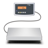
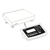
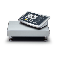
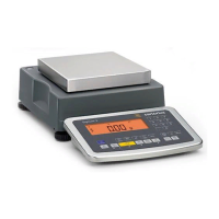
Description of Combics scales features, practical functions, and display layout.
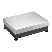
Information on housing specifications and detailed dimensions of CAS platforms and indicators.
Information on pre-installed special equipment for Combics indicators.
Steps for mechanical preparation, including setup, leveling, and connections.
Notice on material damage from vibrations and caution against injury during lifting.
Guidelines for selecting an installation location, avoiding environmental influences.
Procedure for unpacking devices, including safety precautions and checking for damage.
Instructions for removing transport locks on specific CA...G models.
Procedure for leveling the weighing platform using adjustable feet for accurate results.
Instructions for acclimatizing the device in a warm environment to prevent condensation.
Information on connecting peripheral devices, including cables and interface assignments.
Instructions for assembling cables, including torque specifications and notices.
Detailed pin assignments for COM1 digital PCB and COM1 terminal assignments.
Procedure for closing the indicator after making connections.
Information on connecting the device to AC power, voltage range, and integrated power supply.
Information on maximum load limits for weighing platforms depending on load position.
List of available accessories, including printers and optional interfaces.
Using Combics 1 for weight recording, configuring via menu, and keypad operation.
Procedure for switching on the device, including self-test and entering measurement mode.
Requirement for a warm-up time of at least 30 minutes for accurate results.
Steps to enter menu mode for basic settings.
Overview of individual basic settings grouped into categories.
Information on scale configuration, including service mode activation and parameters.
Accessing service mode for additional settings and important adjustments/calibrations.
Step-by-step guide to activating the service mode, including entering a service access code.
Procedure for entering calibration and linearization weights.
Procedure for performing external linearization, especially for scales used in legal metrology.
Setting and selection applications for the scale's functions.
Key assignment for the Fn key and its functions.
Adjusts device settings to user requirements.
Settings for weighing platform 1.
Settings for the RS-232 interface.
Settings for the second optional interface (UniCOM).
Printout settings.
User password entry for locking the Setup menu.
Description of weighing application, including zeroing, taring, and display switching.
Procedure for automatic taring and its activation via menu.
Settings for device parameters like password, acoustic signal, and display.
Explanation of calibration vs. adjustment and procedures.
Step-by-step guide for performing external calibration using standard weights.
Requirements and procedure for internal calibration and adjustment.
Function to display minimum sample quantity according to USP guidelines.
Overview of available applications and functions like weighing, data transfer, and label printing.
Defining scope for each measurement protocol and available parameter settings.
Overview of COM1 (RS-232) and optional UniCOM data interfaces and their characteristics.
Specifications for serial, analog UniCOM, and connection options.
Setting up data interfaces as communication interfaces for various protocols.
Format for control commands sent to the device via the data interface.
Layouts for data output with 16 or 22 characters, including special operations.
Configuring COM1 and UniCOM interfaces for printer connection.
Function to add GMP header and footer to print protocols.
Examples of print protocols for weighing, linearization, calibration, and preload.
Information on regular maintenance performed by Minebea Intec for continued accuracy.
Guidelines for repairs, emphasizing the need for specialists and authorized personnel.
Instructions for cleaning device components, including indicator and stainless steel surfaces.
Procedures for safety checks if the device shows damage or has been stored improperly.
General technical specifications including display, housing, power supply, and safety standards.
Accuracy class, scale intervals, and interface specifications for CAW* P/S models.
Table detailing weighing capacity, readability, and ranges for various CAW model types.
Table showing resolutions for CAW*S models across different weighing ranges and versions.
Reference devices CAS1E and CAS1G with specifications like capacity, readability, and dimensions.
Identification plates and markings on the device, including metrological data and protective seals.
List of certificates related to the device, including EU declarations and evaluation certificates.
List of accompanying documents, including operating and installation instructions.
Description of Minebea Intec's service packages, including installation and verification.
Procedure for entering access codes, including character selection and confirmation.
Explanation of symbols for metrological data: Max, Min, e, d.
Explanation of protective mark (self-adhesive mark or seal).
Explanation of the type plate symbol.
Diagram showing the menu access switch states: unlocked and locked.
Guidelines for power connection, data transfer, and equipment suitability in explosion-risk areas.
Requirements for authorized specialists, environmental conditions, and safe opening procedures.
Guidelines for power connection, cable integrity, potential equalization, and data cable protection.
Rules for installation checks, handling improper operation, using spare parts, and modifications.
| Brand | Minebea Intec |
|---|---|
| Model | Combics 1 Series |
| Category | Scales |
| Language | English |