Do you have a question about the Minebea Intec Combics Series and is the answer not in the manual?
Provides information on maintenance, calibration and error messages for Combics series devices.
Explains the meaning of symbols used in the instructions for better overview.
Details safety precautions for handling and repairing Combics devices to prevent damage or injury.
Provides an overview of the Combics series, including its upgraded features and advice for service courses.
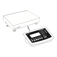
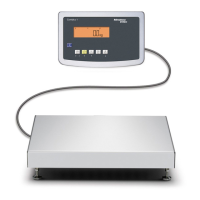
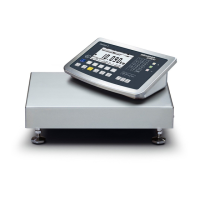
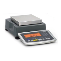
Lists and describes Minebea Intec Combics indicator units and complete scales used in industrial applications.
Lists necessary auxiliary tools and emphasizes the need for a clean, stable workspace for service.
Lists specific tools required for servicing Combics devices, such as multimeter and interface converters.
Details the key functions for different Combics indicator models (CAIS1, CAISL1, CAIS2, CAISL2, CAIS3, CAISL3).
Explains the function of the verification access switch for service software and ADC configuration.
Guides on how to activate the service mode for accessing expanded setup menus and calibration.
Describes the menu items available in Text and Setup menus when the service mode is active.
Instructions on how to exit the service mode by turning the indicator off and on again.
Explains that service mode provides access to additional menu items not visible in standard operation.
Details the procedure for configuring the A/D converter for Combics 1 and 2, including standard and verifiable modes.
Describes a quick installation option for connecting weighing platforms (WP 1 or WP2) to Combics 1 or 2.
Provides steps for configuring the A/D converter for Combics 3, including password entry and menu navigation.
Explains XBPI protocol settings for adjustment routines using service software without activating BPI mode.
Details the test program sequence for Combics 1 and 2 indicators, covering display, keypad, and internal components.
Outlines the test program sequence for Combics 3 indicators, similar to Combics 1 and 2.
Lists common error and information messages displayed on the Combics main display and their causes/solutions.
Details the main PCB for IP44 and IP69 versions, listing UNICOM and ALIBI MEMORY options for CAIS1, CAISL1.
Details the main PCB for IP44 and IP69 versions, listing UNICOM and ALIBI MEMORY options for CAIS2, CAISL2.
Details the main PCB for IP44 and IP69 versions, listing UNICOM and ALIBI MEMORY options for CAIS3, CAISL3.
Shows combinations of Combics PCBs with various options like ADC, RS232, and RS485.
Step-by-step guide on how to open Combics indicators for repair, including safety notes.
Instructions for checking and replacing the seal on Combics indicators to maintain IP degree of protection.
Guidance on replacing the front plate if the keypad or display is defective, covering different versions.
Troubleshooting steps for a blank display, focusing on power supply interruption and voltage checks.
Procedure for replacing the power supply PCB, including disconnection and reconnection steps.
Identifies measuring points on the main PCB for checking supply voltages against ground.
Identifies measuring points on the digital PCB for checking various voltage levels.
Instructions for replacing the power supply connection cable and checking voltage supply.
Procedure for replacing the main/digital PCB, including reading calibration data and software loading.
Details the pin assignments for screw terminals on the main/digital PCB for CAIS(L) models.
Pin assignment for the ADC Option (A8) for Combics 1, 2, and 3, using DSUB or screw terminals.
Pin assignment for the ADC Option (A10/A20) for Combics 1, 2, and 3, using DSUB or screw terminals.
Pin assignment for RS-232/485 interface options (A6/A7) for Combics 1, 2, and 3.
Pin assignment for RS-232/485 interface options (A62/A72) for Combics 2 and 3.
Pin assignment for the UNICOM RS-232 Interface (Option A1) slot.
Pin assignment for UNICOM RS-422/RS-485 Interface (Options A2/A3), including switch settings.
Assignment details for the Digital I/O PCB connected to the UNICOM interface slot.
Configuration options for the UNICOM 4-20mA / 0-10V interface (Option A9) using switches.
Description of the Profibus Option (B1) for UNICOM interface, including clamping connectors and switches.
Description of the Ethernet Option (B9) for UNICOM interface, including clamping connectors.
Details the DeviceNet interface module, equipment supplied, assembly, and operation.
Illustrates the installation steps for the DeviceNet interface module and its connection to the mainboard.
Provides the pin assignment for the DeviceNet interface, detailing connections for V-, CAN_L, SHIELD, CAN_H, V+.
Diagram showing components of the front plate, including complete plates for Combics 1, 2, 3, seal, and tag holder.
Illustrates various PCBs for Combics, including main PCBs, digital PCBs, interface PCBs, and power supply modules.
Diagram showing lower part components like small parts set and power cord for Combics indicators.
Describes the test loads used for various tests, including those for legal metrology as per OIML R111.
Defines an 'Error' as the difference between the indicated value and the actual value of a test load.
Outlines the general procedures for conducting weighing instrument tests.
Details the procedure for testing repeatability, including loading cycles, zero setting, and tolerance checks.
Explains how to test eccentricity by placing loads at different areas and checking indications against tolerances.
Describes tests for weighing performance, including loading/deloading at multiple test loads and error checks.
Guides on calculating and applying resistance values for adjusting off-center load performance.
Provides a sample calculation for determining the required resistance based on load cell readings.
Details techniques for reducing weighing platform deviations for off-center loads by filing strain-gage load cells.
Explains the effect of material removal on measured values and correction possibilities for corner load errors.
| Protection Class | IP65 |
|---|---|
| Display | LCD |
| Interface | RS232 |
| Legal-for-trade | Yes |
| Material | Stainless steel |
| Power Supply | AC adapter or rechargeable battery |