61
Service Manual Combics
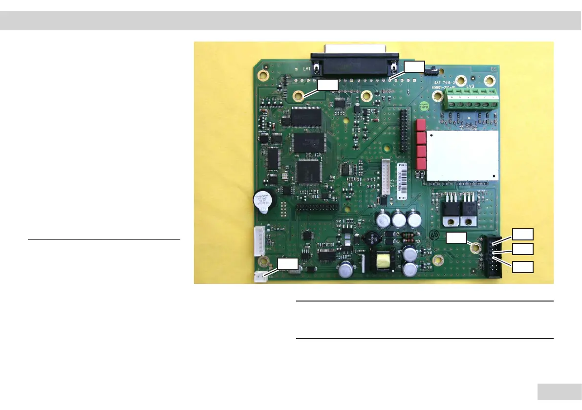
Main PCB Measuring Points
Note:
The voltages are measured
using a digital voltmeter
(DC setting) against the
ground.
Because there are no special
measurement points, the
checks must be made with
the greatest care using a
thin test probe (danger of
a short circuit). The various
supply voltages can be
measured at the following
measurement points.
M1
GND
GND
M2
M3
M4
Important!
h
If no voltages are registered at the measurement points,
then replace the main PCB.
M 1: 15 V ±1.5 V input voltage for the DC/DC converter
M 2:
+3.3 V
±
0.2 V
M 3:
+8.5 V
±
0.4 V
M 4:
-8.5 V
±
0.4 V
M 5:
5 V
±
0.25 V
h
Repairs | Component Replacement | Measurement Points
M5
 Loading...