Do you have a question about the Minebea Intec CAS-SPC Series and is the answer not in the manual?
Explains the meaning of symbols and signs used throughout the manual.
Provides contact information for technical support and application advice.
Details ingress protection ratings for various Combics scale models.
Guidelines and regulations for operating the scale in legal metrology.
Specifies the recommended applications for the Combics 3 scale.
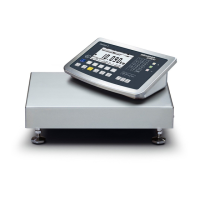
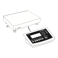
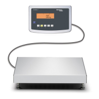
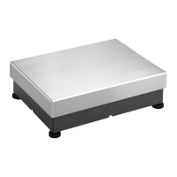
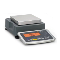
Identifies key parts of the weighing platform.
Identifies key parts of the indicator unit.
Details the connections and ports on the rear of the indicator.
Guidelines for proper storage and transport of the equipment.
Advice on selecting an appropriate location for installation.
Steps for unpacking and verifying all included items.
Instructions for removing transport locks on CAS3-G models.
Procedure for ensuring the weighing platform is properly leveled.
Specific leveling instructions for IGG models.
Details maximum load capacities for various platform sizes.
Information on platform durability and superstructure planning.
Explanation of preload settings and device acclimatization.
Overview of the initial procedures for setting up the scale.
Guidance on connecting external devices and weighing platforms.
Procedures for installing and preparing interface cables.
Instructions for routing cables through the gland for IP protection.
Specific steps for connecting IS weighing platforms to Combics 3.
Overview of connecting peripherals and second platforms.
Pinout details for various interface PCBs (Digital, RS-232/485, ADC).
Detailed pinout for the COM1 interface (25-pin D-Sub).
Steps for establishing a PC connection using the COM1 interface.
Visual guide to COM1 pin assignments for PC connection.
Detailed pinout for the COM2 interface (9-pin D-Sub).
Steps for establishing a PC connection using the COM2 interface.
Pinout details for the PS2 interface (Mini-DIN).
Instructions for connecting a barcode scanner via PS/2.
Procedures for connecting the scale to AC power.
Critical safety information regarding power connections.
Recommendations for warm-up and use in legal metrology.
Accessing and exiting the service mode for advanced configuration.
Hierarchical overview of the setup menu options in service mode.
Settings for weighing platforms, interfaces, and calibration.
Settings related to the SQmin function for sample quantity.
Detailed menu structure for A/D converter setup.
Process for configuring the ADC for load cells.
Detailed parameter settings for ADC configuration.
Defining weighing ranges, intervals, and maximum capacity.
Selecting display units and saving ADC configuration.
Step-by-step guide for configuring the ADC.
How to open and use the menu access switch.
Detailed steps for setting up a single weighing range.
Setting up multiple weighing ranges with different readabilities.
Enabling or disabling weight units for display.
Defining the unit for calibration and adjustment processes.
Procedure for saving the configured ADC settings.
Steps for configuring ADC after load cells are connected.
Inputting location data for external adjustments in legal metrology.
Prerequisites and menu path for entering geographical data.
Procedure for inputting geographical latitude and elevation values.
Inputting the gravitational acceleration value.
Steps for adjusting scales outside the service menu.
Step-by-step guide for carrying out an external adjustment.
Further steps and confirmations for the external adjustment process.
Procedure for setting weights for calibration and linearization.
Assigning calibration and adjustment functions to the J key.
Performing external calibration using a factory-defined weight.
Detailed steps for the external adjustment process.
Performing external calibration using a user-defined weight.
Detailed steps for the user-defined external adjustment.
Performing calibration and adjustment without external weights.
Procedure for adjusting the scale using load cell data.
Entering nominal capacity, resolution, and sensitivity values.
Procedure for saving the configured weighing parameters.
Assigning preload setting/deletion functions to the J key.
Steps for performing external linearization with default weights.
Steps for performing external linearization with user-defined weights.
Final steps and printout after completing linearization.
Step-by-step guide for setting the preload value.
Step-by-step guide for deleting the preload value.
Overview of the display and controls in weighing mode.
Description of the functions assigned to the keys.
Explanation of symbols and abbreviations for soft keys.
How to enter numbers and text using the keypad.
Procedures for entering spaces, special characters, and deleting input.
How to save settings and apply tare weight.
Connecting external switches via the digital control port.
Components and layout of the weighing display.
Explanation of symbols used on the display.
Types of data displayed, including tare, calculated values, and platform ID.
Icons indicating application status, printing, and battery level.
Interpreting LEDs, error codes, and navigating menus.
How to retain settings after configuration.
Overview of configurable parameters in the setup menu.
Procedure for changing the device's display language.
Steps to secure device and application parameters with passwords.
Procedures for setting and deleting passwords.
Configuration options for printout parameters.
Hierarchical view of all configurable parameters.
Configuration options for the internal settings of Weighing Platform 1.
Further internal settings for WP 1, including weight units and display accuracy.
Settings for multiple weighing platforms (WP 1, WP 2).
Configuration options for the COM 1 interface.
Detailed settings for data communication via COM 1.
Configuration options for printers connected to COM 1.
Configuration for COM 2 and optional UNICOM interfaces.
Settings for analog output signals (voltage/current).
Configuration for input/output ports and universal switch keys.
Configuration for barcode scanning and printout content.
Specific settings for number of printouts, single printouts, and data records.
Settings for acoustic signal, keypad, display, and automatic shutdown.
Configuration of various device parameters like clock, I/O, and passwords.
Summary of setup sections including Info, Service, Terminal, and Language.
Fundamental steps for performing weighing operations.
Explanation of soft key usage during operation.
Initial steps and menu selections before starting weighing.
How the scale automatically tares containers and sets values.
Setting up automatic printing based on stability or minimum load.
Using a barcode scanner for tare entry and parameter input.
Explanation of counters for tracking parameter changes.
Overview of settings for password, signal, keys, and display.
Step-by-step procedure for taring the scale with a container.
Entering tare values numerically and printing results.
Procedure for printing weighing results and GMP footers.
Using multiple tare values and printing results.
Printing the net weight and clearing tare values.
Performing calibration and adjustment for accuracy.
Settings required for legal metrology compliance.
Details on internal, external, and blocked calibration features.
Performing external calibration using factory default weights.
Steps to complete and verify external adjustment.
Steps for performing internal calibration and adjustment.
Purpose and features of the SQmin function for sample quantity.
Entering and configuring SQmin values in service mode.
Enabling and viewing the SQmin display in weighing mode.
Steps for performing weighing with SQmin monitoring.
How to assign names and values to ID codes for identification.
Examples and procedures for entering ID code names and values.
Details on COM1, COM2, and UniCOM interfaces.
Technical details for serial interfaces (RS-232, RS-485).
Specifications for the optional analog UniCOM interface.
Details on connecting printers, PCs, and additional weighing platforms.
Steps to configure data interfaces as COM ports (SBI, XBPI, SMA).
Configuring automatic or manual data output via SBI.
Structure and format for sending commands to the scale.
List of commands and their meanings for data transfer.
Mapping PC keyboard keys to scale functions.
Explanation of data output formats with and without ID codes.
Detailed structure for data output including ID codes.
List of error codes, their meanings, and status indicators.
Detailed mapping of PC keyboard keys to scale functions.
Steps to configure the data interface as a printer port.
Customizing printout headers, date/time, and identifiers.
Setting up identifiers for printout customization.
Enabling and configuring GMP headers and footers for printouts.
Examples of printouts for Weighing and Counting applications.
Sample printouts for Neutral Measurement and Weighing in Percent.
Example of printout for checkweighing with tolerance results.
Examples of component printouts and standard printouts.
Examples of GMP printouts for linearization, calibration, and preload.
Examples of printouts for preload deletion and multiple weighing results.
Detailed list of error codes, causes, and solutions.
Information on professional servicing and repair procedures.
Instructions for cleaning the weighing platform and indicator.
Specific cleaning guidelines for stainless steel parts.
Procedure for replacing a damaged dust cover.
Checks to ensure the safe operation of the device.
General technical data including display, housing, and environmental ratings.
Technical specifications tailored to specific Combics models.
Resolution details for various CAW*S models.
Technical data for CAS reference devices.
Technical data for CASLE and CASE models.
Dimensional drawings for CAS*E weighing platforms.
Dimensional drawings for CAS*G FE weighing platforms.
Dimensional drawings for CAS*G IG weighing platforms.
Dimensional drawings of the indicator unit.
Dimensional drawings for the CASE-SPC-06HCE model.
Dimensional drawings for CASE-SPC-3HCE and CASLE-SPC-6HCE models.
Dimensional drawings for CASE-SPC-16HCE and CASLE-SPC-35HCE models.
Details on printers and connection cables for Combics.
List of mechanical accessories and various connection cables.
Catalog of available operating instructions and documentation.
Information on installation, verification, and customer services.
Certificate details for EU type examination.
Details from the test certificate.
Details from the evaluation certificate.
Description of plates and marks on CAW models.
Examples of indicator model plates and metrological data labels.
Examples of labels showing metrological data for additional receptors.
Description of plates and marks on CAS1/3E models.
Description of plates and marks for Typ ISED models.
Description of plates and marks for Typ BD SI models.
Description of plates and marks on CASE-SPC models.
Description of plates and marks on CASE-SPC models.
Description of plates and marks on CASLE-SPC models.
Description of plates and marks on CASLE-SPC models.
Description of plates and marks on CASLE-SPC models.
Description of plates and marks on CASS-SPC models.
Description of plates and marks on CASS-SPC models.
Description of plates and marks on CASS-SPC models.
Description of plates and marks on CASS-SPC models.
Description of plates and marks on CASS-SPC models.
Description of plates and marks on CASS-SPC models.
Description of plates and marks on CAS1/3G models.
Description of plates and marks on CAS1/3G models.
Description of plates and marks on CAS1/3G models.
Description of plates and marks on CAS1/3G models.
Specifies EX area types, power connection, and data transfer guidelines.
Guidelines for connecting platforms and external devices in EX zones.
Comprehensive safety guidelines for installation, use, maintenance, and repair.
Detailed safety measures for installation, electrical interference, and connections.
Documents required for weighing instrument verification.
Guidance on filling out and using the compatibility evidence program.
Procedures for setting and managing the service password.
Procedures for setting and managing the general password.
| Type | Checkweigher |
|---|---|
| Model Series | CAS-SPC Series |
| Power Supply | 100-240 VAC, 50/60 Hz |
| Protection Class | IP65 |
| Readability | 0.1 g to 1 g |
| Accuracy | ±0.1 g to ±1 g |
| Throughput | Up to 300 products/min |
| Communication Interfaces | Ethernet, RS-232, Digital I/O |
| Display | Color touchscreen |
| Software | Statistical software for data analysis and reporting |