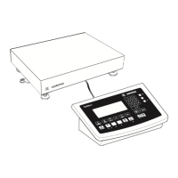
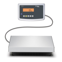
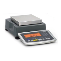
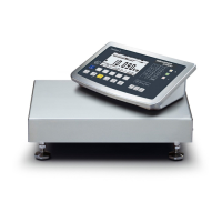
Keypad
+ Display
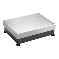
Weighing platform
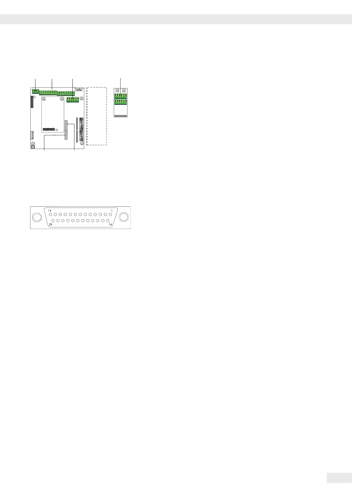
Interface 1
Interface PCB for RS-232/485 for IS weighing platform
(option A62/A72)
Interface PCB A6/7 and A62/72
1 CTS 11 TxD/RxD+
2 DTR 12 TxD/RxD-
3 RxD 13 LINE_OUT
4 TxD 14 LINE_OUT
5 GND 15 GND
6 Adjustment Lock 16 GND
Keys
LED + Display , A Alibi memory
Interface Pin Assignment Chart COM1
Model type CAW3P | CASLE-SPC (IP44 protection)
COM1 female connectors:
25-pin D-Submini female connector (DB25S) with screw lock hardware for cable
gland
Recommended interface connector:
25-pin D-Submini (DB25) with shielded cable clamp assembly and shield plate
(Amp type 826 985-1C) and fastening screws (Amp type 164868-1)
COM1 pin assignments
Pin 1: Shield
Pin 2: Data output (TxD)
Pin 3: Data input (RxD)
Pin 4: GNO
Pin 5: Clear to send (CTS)
Pin 6: Not assigned
Pin 7: Internal ground (GND)
Pin 8: Internal ground (GND)
Pin 9: Not assigned
Pin 10: Not assigned
Pin 11: +12V for printer
Pin 12: RES_OUT\
Pin 13: +5 V switch
Pin 14: Internal ground (GND)
Pin 15: Universal switch
Pin 16: Control output: “lower“
Pin 17: Control output: “equal“
Pin 18: Control output: “heavier“
Pin 19: Control output: “set“
Pin 20: Data terminal ready (DTR)
Pin 21: Ground power supply (GND)
Pin 22: Not assigned
Pin 23: Not assigned
Pin 24: Power supply +15..25 V (peripherals)
Pin 25: +5 V
Operating Instructions Combics Complete Scales 15
Getting Started
A
 Loading...