Getting Started
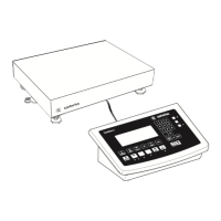
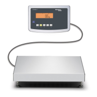
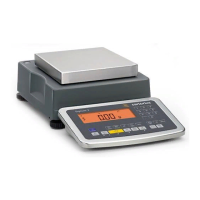
Steps 1.) Set up the weighing platform with the indicator.
2.) Level the weighing platform
3.) Connect peripheral devices, e.g. printer to the COM1 or UNICOM interface:
see Data Interfaces chapter starting on page 99
4.) Connecting the device to AC power
5.)
Carry out an alignment: for adjustment, see page 27, for linearization see page 24
Connecting Peripheral Devices or Another Weighing
Platform
An analog Minebea Intec IS weighing platform is connected at the factory to the
Combics indicator WP1 input.
3
The load cell should be connected by a certied technician who has received
specialized training from Minebea Intec. Any installation work that does not
conform to the instructions in this manual results in forfeiture of all claims under
the manufacturer’s warranty.
3
Peripheral devices should be connected by a certied technician who has received
specialized training from Minebea Intec. Any installation work that does not
conform to the instructions in this manual results in forfeiture of all claims under
the manufacturer’s warranty.
3
Disconnect the equipment from the power supply before starting connection work.
t Place cables from peripheral devices next to the indicator.
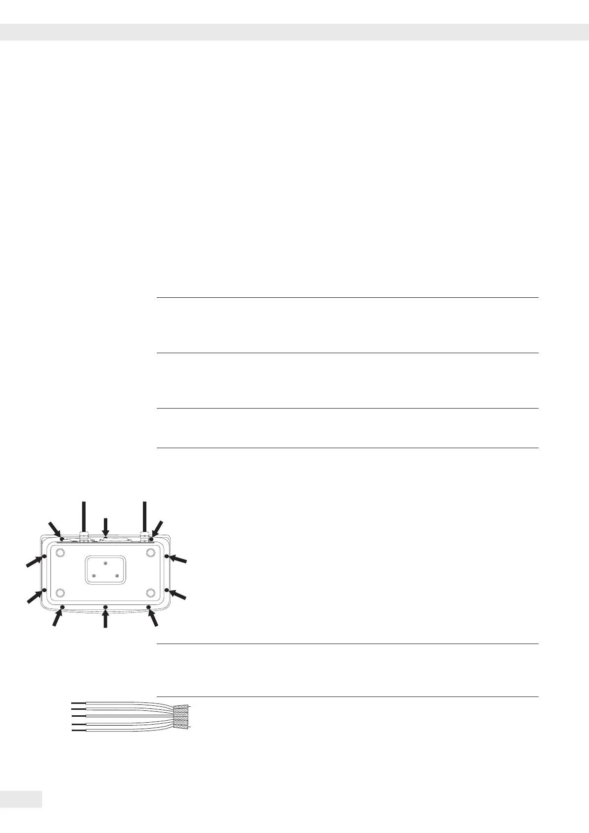
CAW3S, CAS3 (IP69K) t Opening the Combics indicator:
Loosen the ten cap nuts on the front panel. Remove the front panel.
Installing Connection and Interface Cables
3
The cable gland (IP69K protection) is pre-mounted on the indicator. Please use
extreme caution when performing any work on the equipment that aects this
cable gland.
You must use a torque wrench. The torque for this cable gland is 5 Nm.
Preparing Cables
t Strip approx. 14 cm from the end of the cable.
t Shorten the shielding to approx. 2 cm and pull back over the insulation.
t Strip approximately 5 mm of the insulation from the wires of the connecting
cable and ax ferrules to the wire ends.
Getting Started
12 Operating Instructions Combics Complete Scales
 Loading...