Attaching the Cable Entry
3
Please use extreme caution when performing any work on the equipment that
aects this cable gland.
You must use a torque wrench.
The torque for this cable gland is 5 Nm.
4
1
5
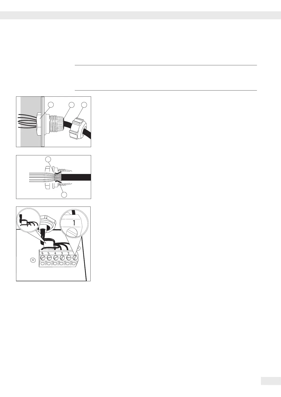
t Remove the protective cap from the bore hole on the indicator.
t Insert the included cable gland through the bore hole and secure from the inside
using the locknut (1).
t Insert the cable through the cable gland until the shielding (2) comes into
contact with the clamps (3). Tighten the screw-down nut (4) until the gasket (5)
inserted between the screw-down nut and cable forms a small beaded rim.
t Check the shielding and clamps.
t Securely connect the wires of the connecting cable in accordance with the
terminal assignments.
t After you close the housing again, use a pressure gauge to check the integrity of
the IP69K protection. For details, contact the Minebea Intec Service Center.
Connecting Cables
t Insert all cable wires through the ferrite case, wind them around the ferrite case
and then reinsert back through the ferrite case.
t Screw the wires tightly into the clamps.
See the following pages for terminal pin allocation
t Refer to the data sheet or operating instructions of the
weighing platform for details on the assignment of wire
colors/signals. Ensure any lines that are not assigned
are insulated correctly.
t When connecting a load receptor that uses 4-conductor technology (the cable
of the weighing platform to be connected only has 4 lines), connect clamp
pairs 1 and 2 (EXC+ und SENSE+), and 5 and 6 (SENSE- und EXC-) with a wire
jumper.
Connecting an IS Weighing Platform to a Combics 3
You can connect an IS weighing platform to WP2.
Features – IS weighing platforms process weighing data independently of the indicator.
– Internal adjustment option
– IS...-0CE models: have a separate approval number, printed on a tag that is
axed to the cable.
– Please observe the conditions described in the manual for the weighing platform
you connect.
Getting Started
Operating Instructions Combics Complete Scales 13
 Loading...