133
15-1-4. Calibration mode of zero point only
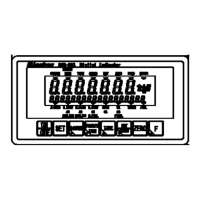
The items in the flowchart correspond to the steps in [4-6 Calibration only of zero point].
For details, refer to [4-6 Calibration only of zero point].
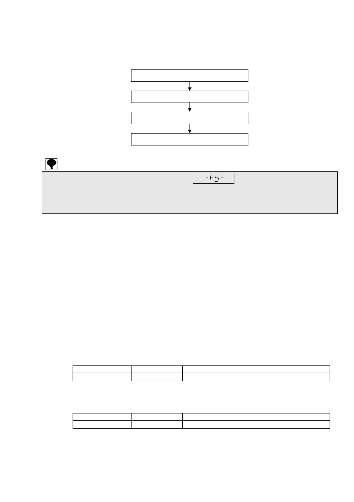
・ While executing the calibration by transmission, (–RS–) is displayed.
・ When the calibration is compulsorily finished, all the data returns to the condition before the
calibration without executing the registration.
・ Please register the data for the calibration with the weight after confirming the stable condition
without fail.
(1) Changing to calibration mode of zero point only
Write 12 to maintenance address 56853, and proceed to calibration mode of zero point only.
(2) Zero stability check
Stable/Unstable is read out from holding register address 56845 with no load on the measuring
section.
0 : Unstable 1 : Stable
(3) Calibration at zero by measurement value
The load cell output value is registered in holding register address 72 as the zero point.
[1] is written in holding register address 72.
[1] is automatically rewritten as [0] after writing is normally completed.
Setting range : 1
TE-L error
[20] (TE-L) is written in input register address 52 when the read load cell output value is less than -2.5
mV/V which exceeds the range of zero adjustment on a minus side.
Condition Error code Contents
TE-L
-
(Zero point) < (-2.5 mV/V)
TE-H error
[21] (TE-H) is written in input register address 52 when the read load cell output value is more than
2.5 mV/V which exceeds the range of zero adjustment on a plus side.
Condition Error code Contents
TE-H
-
(2.5 mV/V) < (Zero point)
(1) Changing to calibration mode of zero point only
(2) Zero stability check
(3) Zero calibration using weight
(4) Ending calibration mode of zero point only
 Loading...