Dowel Drill Manual
14
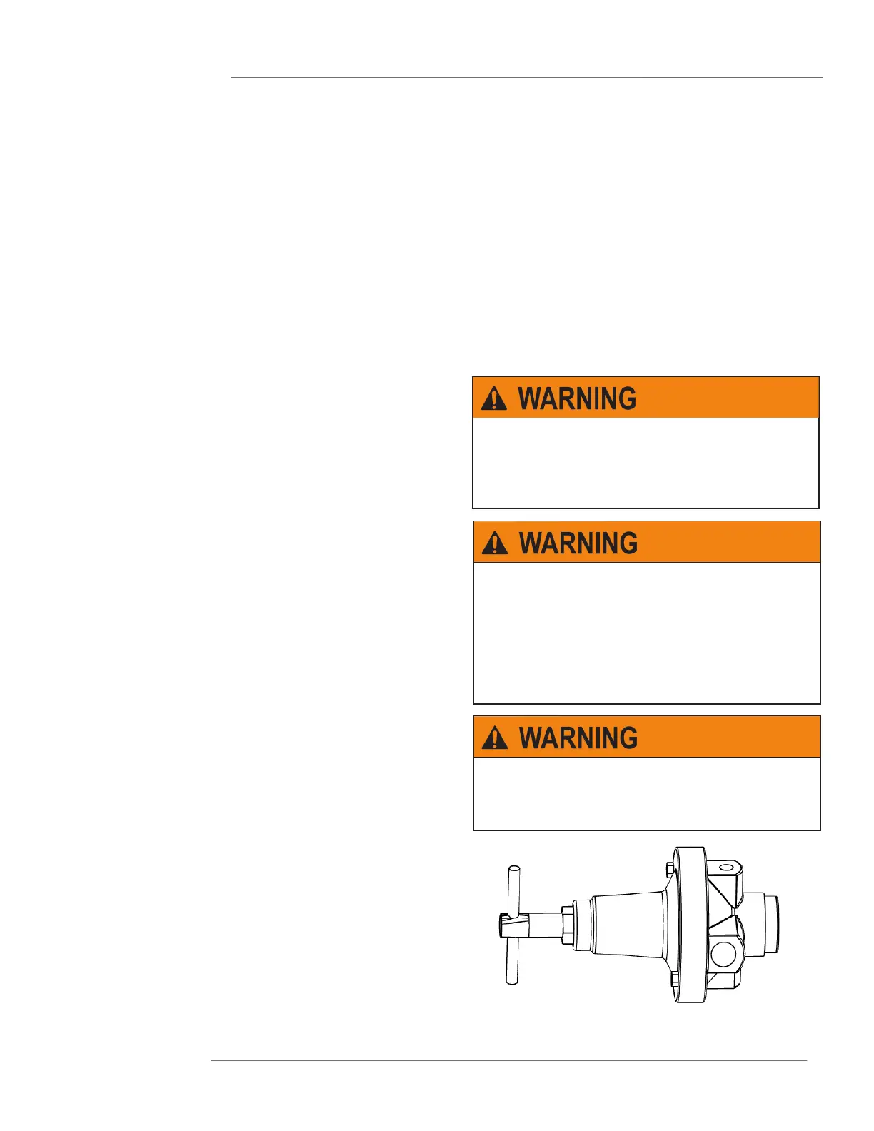
PRESSURE REGULATOR
OPERATION
ADJUSTMENT
MAINTENANCE
A regulator is used in a compressed air system to maintain nearly constant outlet pressure despite changes in the inlet air pressure and
changes in downstream ow requirements. Outlet pressure is controlled by the adjusting screw (1). clockwise rotation increases and
counter- clockwise rotation decreases outlet pressure setting. When the adjustment (1) is rotated fully counter- clockwise, no force is ap-
plied to the regulating spring (2), and the valve (6) is held closed by the valve spring (7). clockwise rotation of the adjustment (1) compresses
the regulating spring (2) which applies a downward force on top of the diaphragm (4). The diaphragm (4) and valve pin (5) move downward
forcing valve (6) off its seat (10) which allows air to ow through the regulator to the downstream system. Outlet pressure increases in the
downstream system and sensing chamber (9) and applies an upward force on bottom of the diaphragm (4). The diaphragm (4), valve pin (5);
and valve (6) move upward, compressing the regulator spring (2). Upward movement stops when the forces below the diaphragm balance the
forces above the diaphragm. When there is no downstream ow demand, the balance of forces occurs with the valve (6) closed. When there
is downstream ow demand, the balance of forces occurs when the valve opens sufciently to compensate for demand, thus maintaining the
desired outlet pressure. RELIEVING TYPE REGULATORS. With relieving regulators, outlet pressure can be reduced even though the system
is deadended. When the adjustment (1) is turned counterclockwise, the force on the regulating spring (2) is reduced, and air pressure in the
sensing chamber (9) moves the diaphragm (4) upward. This upward movement opens the relief passage (8) in the diaphragm and allows air to
escape from the outlet side of the regulator through the relief passage (8) and vent (3) to atmosphere. As the outlet air pressure decreases to
the reduced pressure setting, the diaphragm moves downward and closes the relief passage. The diaphragm will likewise move upward in a
response to an increase in outlet pressure above the regulator setting, allowing air to escape to the atmosphere as described above. Howev-
er, the ow capacity of the relief passage is limited, and depending upon the source of the overpressure condition, the outlet pressure might
increase to a point signicantly higher than the regulator setting. For this reason, the relief feature of a regulator must not be relied upon as an
overpressure safety device. See WARNING note below.
1. Before turning on system air pressure, turn regulator adjustment coun-
terclockwise until all load is removed from regulating spring.
2. Turn on system air pressure.
3. Turn regulator adjustment clockwise until the desired outlet pressure is
reached.
4.To avoid minor readjustment after making a change in pressure setting,
always approach the desired pressure from a lower pressure. When re-
ducing from a higher to a lower setting, rst reduce to some pressure less
than the desired, then bring up to the desired point.
5. Tighten jam out to lock pressure setting.
The regulator can be disassembled for servicing without removal from
pipe line. to disassemble, shut off the inlet air and reduce pressure in
inlet and outlet lines to zero. Turn adjusting screw (1) counterclockwise
until all load is removed from regulating spring (7 or 7a): Remove bonnet
screws (4), bonnet (3), upper springrest (5), spring (7), and diaphragm as-
sembly (8). The intermediate springrest (6) and compound spring (7a) are
used only on 3/4” (19mm) and 1” (25.4mm) models with 5 to 125 PSI (0.34
to 8.62 Bar) adjustment range. Unscrew and remove bottom plug (16),
O-ring (15) and valve spring (14). Pull valve assembly (11) together with
O-ring (12) out of body. Do not remove valve seat (10) unless replace-
ment is necessary. Remove O-ring (9) using a hook shaped tool, taking
care not to damage O-ring seating surfaces or valve seat. Clean parts
using warm water and soap. Dry thoroughly. Inspect each part carefully.
Replace any parts which are damaged. At reassembly, apply a wipe
coat of silicone base grease to O-rings (9, 12, 15), to stem and body of
valve assembly (11), and to center bore in bottom plug (16). Apply a light
even coat of light grease to full length of threads and tip of adjusting
screw (1). Tighten valve seat (10), if previously removed, to 80-100 inch-
pounds torque (9-11.3 N-m) (1/4”, 3/8” and 1/2” sizes) (6.35mm, 9.53mm,
and 12.77mm sizes) or 25-30 foot-pounds torque (33.9-40.7 N-m) (3/4”
and 1” sizes) (19mm and 25.4mm sizes). Tighten bottom plug (16) snugly
by hand. Tighten bonnet screws (4) to 20-30 inch-pounds torque (2.3-3.4
N-m) (1/4”, 3/8” and 1/2” sizes) (6.35mm, 9.53mm, and 12.77mm sizes) or
50-60 inch-pounds torque (5.6-6.8 N-m) (3/4” and 1” sizes) (19mm and
25.4mm sizes).
THESE REGULATORS ARE INTENDED FOR USE IN
INDUSTRIAL COMPRESSED AIR SYSTEMS ONLY.
DO NOT USE THESE REGULATORS WHERE PRES-
SURE OR TEMPERATURE CAN EXCEED RATED
OPERATING CONDITIONS. SEE SPECIFICATIONS.
IF OUTLET PRESSURES IN EXCESS OF THE
REGULATOR PRESSURE SETTING COULD CAUSE
DOWNSTREAM EQUIPMENT TO RUPTURE OR
MALFUNCTION, INSTALL A PRESSURE RELIEF DE-
VICE DOWNSTREAM OF THE REGULATOR. THE
RELIEF PRESSURE AND FLOW CAPACITY OF THE
RELIEF DEVICE MUST SATISFY SYSTEM REQUIRE-
MENTS.
BEFORE USING WITH FLUIDS OTHER THAN AIR,
FOR NON-INDUSTRIAL APPLICATIONS, OR FOR
LIFE SUPPORT SYSTEMS, CONSULT C.A. NOR-
GREN CO
 Loading...