15
Dowel Drill Manual
STANDARD SETUP
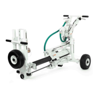
UNLOADING THE UNIT
If you’re A-1C unit is on a truck bed or other
plat-form and needs to be lifted into position,
use the
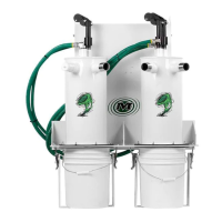
FILLING LUBRICATOR
Prior to lling the lubricator, be sure there is no
air pressure in the unit. Failure to relieve air pres-
sure will result in the ll plug exploding from the
lubricator, which may result in injury.
Remove ll plug and ll with lubricant until sight
gauge is full. Replace ll plug. Lubricator should
be lled every two hours of use for an A-1C. See
Recommended Lubricants chart on page XX for
acceptable lubricants.
MACHINE INSPECTION
Prior to each use, it is imperative to inspect the
machine all over to ensure excellent condition
for the safety of the operator and to prevent
damage to the equipment.
• Check all drill bed bolts and tighten as neces-
sary on a daily basis. Tighten all other bolts at
least once weekly. Refer maintenance diagram
on page 5-1.
• Grease ttings around drill bed daily. Grease
all other ttings at least once a week. Refer
maintenance diagram on page 5-1.
• Verify that all lock pins are in their locked posi-
tion.
• Make sure all controls are in the “off” position
and the lift lever is in the “up” position.
• Check that the air line is cleaned out and is the
proper size and pressure rating.
• Ensure the air compressor is set at an operat-
ing pressure of not more than 120 PSI (8.27bar).
• Install drill steel and bits into the drill motors
and close the latch retainers and rod guides.
AIR COMPRESSOR CONNECTION
• Connect the air line to the drill in accordance
with hose connection instructions in the com-
pressor manual.
• Start the compressor according to manufactur-
er’s instructions.
POSITION MACHINE FOR DRILLING
• Position the drill unit where the rst set of
holes is to be drilled, keeping the drill unit back
from the edge of the slab slightly. Set the brake.
• With the lift lock still engaged, charge the lift
cylinder by toggling the lift lever up and down.
• With the lift valve in the “up” position and after
making sure that there are no obstructions in the
path of the drill bed, remove the lift lock pin.
• Using the lift lever, lower the drill bed into drill-
ing position.
HEIGHT ADJUSTMENT
To check the drilling height, measure from the
top of the slab to the center of the drill steel.
If necessary, loosen the locknuts and use the
ad-justing screws to raise or lower the drill bed
into the proper drilling height. After height is
properly adjusted, re-tighten the locknuts.
Verify the drill bed is parallel with the slab that
is to be drilled into. If necessary, loosen the
locknut on the lift cylinder and turn the adjust-
ing screw right to raise the bed or left to lower
the bed until the bed is parallel with the slab.
Re-tighten locknuts after complete.
DEPTH ADJUSTMENT
Physical motion is going to occur, stand clear of
the drill unit.
To set the drill depth, remove all of the rail lock-
ing pins and feed the drill bit into the face of the
slab without turning on the drills by turning on
Feed 1 and the feed switch. Repeat for Feed 2,
when applicable. Measure the distance between
the drill stop rod and the drill stop pad. Ad-
just the stop bolt so that the distance between
the stop pad and the stop bolt equals the drill
depth.
DRILL TEST HOLE
Refer to operating instructions to drill the rst
set of holes. After the rst set of holes, measure
the height and depth of the hole to ensure prop-
er alignment.
 Loading...