62 Rev 2.2 • 27 Mar 10
2. Installation
Making Signal Connections
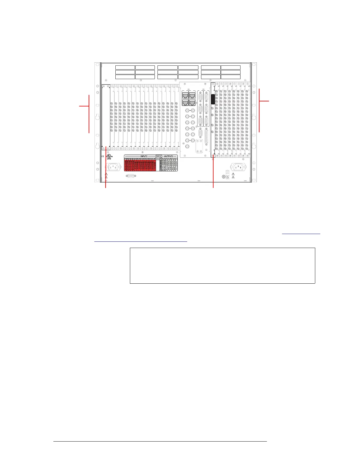
Figure 2-9, shows the backplane locations at the rear of an NV8144 router.
Figure 2-9. NV8144 Frame with DIN 1.0/2.3 Backplanes (Rear View)
2 For each input, connect to an input connector using a DIN 1.0/2.3 connector and 1855A Belden
cable, or an equivalent, or a LC connector and fiber optic cable, or a WECO connector and coax
cable. For details on the signal number assigned to an individual connector, see Backplane Con-
nectors and Individual Signal Numbers on page 14.
Important! LC backplanes are composed of 5 modules of two connectors each for a total of 10
possible connections. Do not connect to all 10 connections. Only 9 of the connectors are used.
Make LC connections as follows:
DIAG (38.4 Kbaud)
CONTROL
IN 1
MONITOR
OUTPUT
IN 2
OUT 2OUT 1
POWER
SUPPLY
i
MONITORS
TIME CODE
NVISION AUX BUS
RTR EXP OUT
RTR EXP IN
AES REF 1
AES REF 2
VIDEO REF 2
VIDEO REF 1
RTR EXP
10/100 BT
RTR EXP
10/100 BT
CTRL 1
CTRL 2
ALARMS
CTRL 1
CTRL 2
DIAG (38.4 Kbaud)
PRI
SEC
SEC
PRI
90-130V~/180-250V~
12.5A/6.25A
50/60Hz
1125 WATT S MAX
PS1
PS2
90-130V~/180-250V~
12.5A/6.25A
50/60Hz
1125 WATT S MAX
E146905
CNTRL NO. 9K50
PROFESSIONAL
VIDEO/AUDIO
ALARMS
Monitor Backplane (1)
Control card area
(no backplanes)
Output
Backplanes (8)
Input
Backplanes (16)
NV8576,
NV8576-Plus
Note
Signals are numbered in ascending order from top-to-bottom. This is true
for backplanes in both the upper region and in the lower region of the
NV8576 or NV8576-Plus frame. Although the backplanes are installed in
“mirrored” position, the signal numbering is identical.