NV8500 family Digital Routers • User’s Guide 63
2. Installation
Making Signal Connections
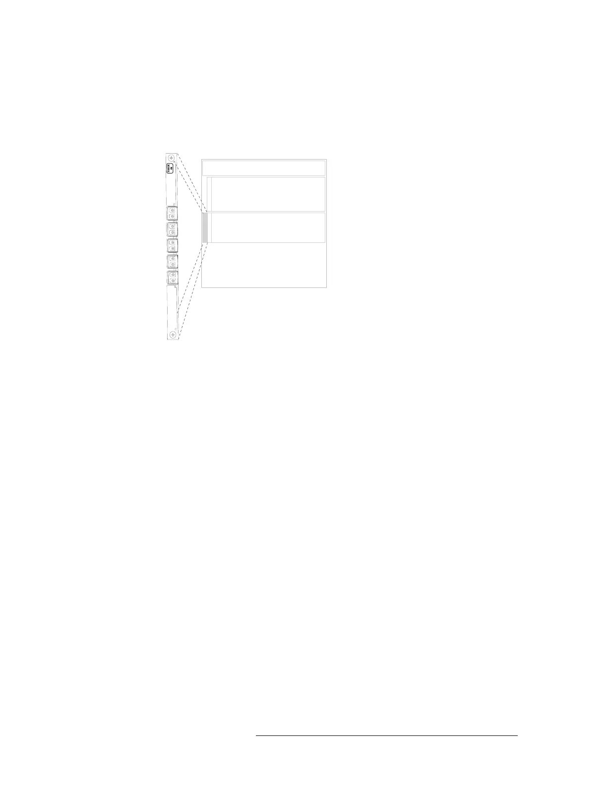
For the NV8144 and the NV8280, the bottom connector is not used. Only connect to the first 9
connectors, starting at the top and connecting to each connector in turn, leaving the remaining
bottom connector empty. See Figure 2-10.
Figure 2-10. NV8280 LC Input Backplanes (Rear View)
For the NV8576, in the upper section of the frame, only connect to the first 9 connectors. Start
at the top and connect to each connector in turn, leaving the remaining bottom connector empty.
In the bottom section of the frame the backplanes are rotated 180° from those in the upper por-
tion and “face” in the opposite direction. Therefore, only connect to the last 9 connectors, start-
Inputs
Outputs
Input Backplanes
1
2
3
4
5
7
8
9
6
Not
used