80 Rev 2.2 • 27 Mar 10
2. Installation
Making Monitor Connections
2 For each connection, use a DIN 1.0/2.3 connector and 1855A Belden cable, or an equivalent
(provided with product package), and make connections as follows:
NV8144
— connect ‘OUTPUT MON’ and ‘INPUT MON’ on the monitor backplane to your
monitoring equipment.
NV8280/NV8280-Plus
— connect ‘OUT 1’ and ‘OUT 2’ on the output monitor backplane to
your monitoring equipment.
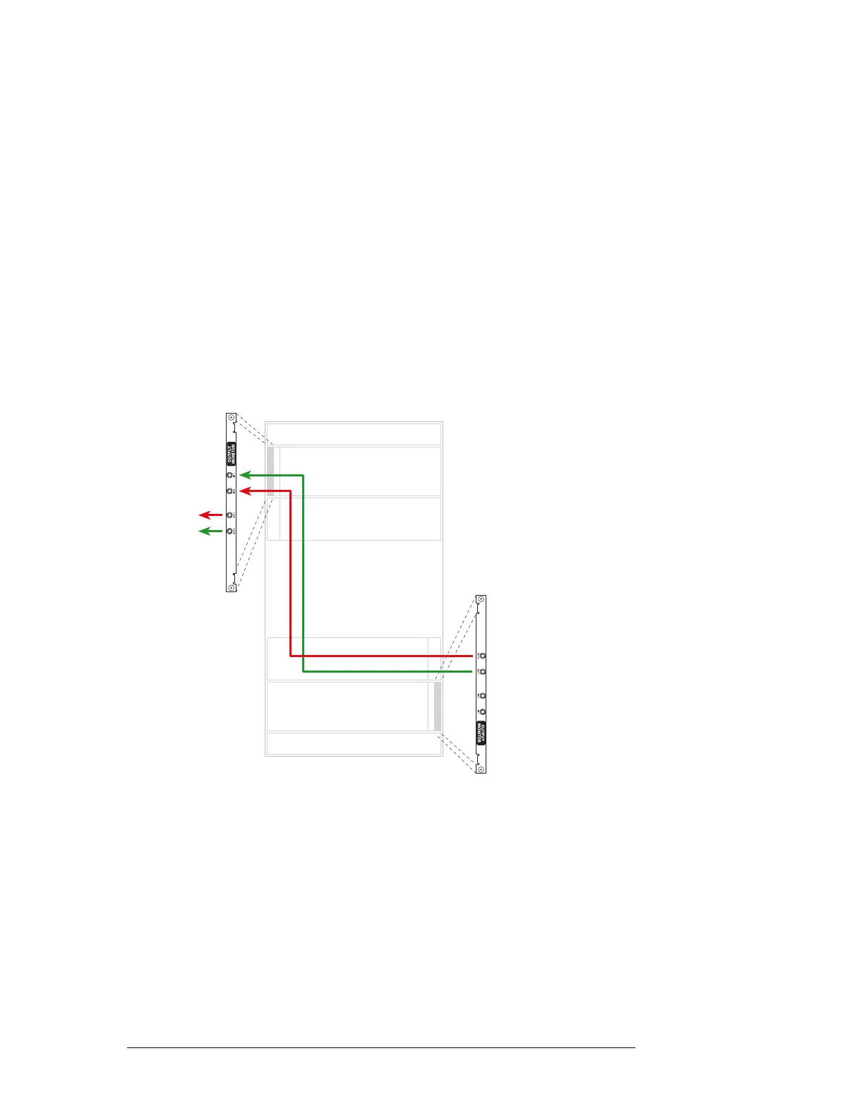
For NV8576/NV8576-Plus:
Connect ‘OUT 1’ of the output monitor backplane in the lower bay, to ‘IN 1’ of the output mon-
itor backplane in the upper bay, as shown in Figure 2-24
Similarly connect ‘OUT 2’ of the output monitor backplane in the lower bay, to ‘IN 2’ of the
output monitor backplane in the upper bay, as shown in Figure 2-24.
Connect ‘OUT 1’ and ‘OUT 2’ of the output monitor backplane in the upper bay to your moni-
toring equipment, as shown in Figure 2-24:
Figure 2-24. Monitor Connections for NV8576(Rear View)
Inputs
Outputs
Inputs
Outputs
To
equipment
1
2