EasyManua.ls Logo

MiTAC Maestro 830 - Connecting to the Internal Headers and Connectors

MiTAC Maestro 830
69 pages
Print Icon
To Next Page IconTo Next Page
To Previous Page IconTo Previous Page
Loading...
J5
LVDS Connector
J1
CMOS Clear
J31
DMIC Cable
J6
Ambient Light Sensor Cable
J21
MiniPCIe slot For WLAN
J22
MiniPCIe slot For SSD/TV card
J11
NFC/RFID
J4
SATA Power Cable
J14
ODD Cable
J30
Front SW/LEDs Y Cable
J15
HDD Cable
J18
Wireless Charging Module
Connecting to the Internal Headers and Connectors
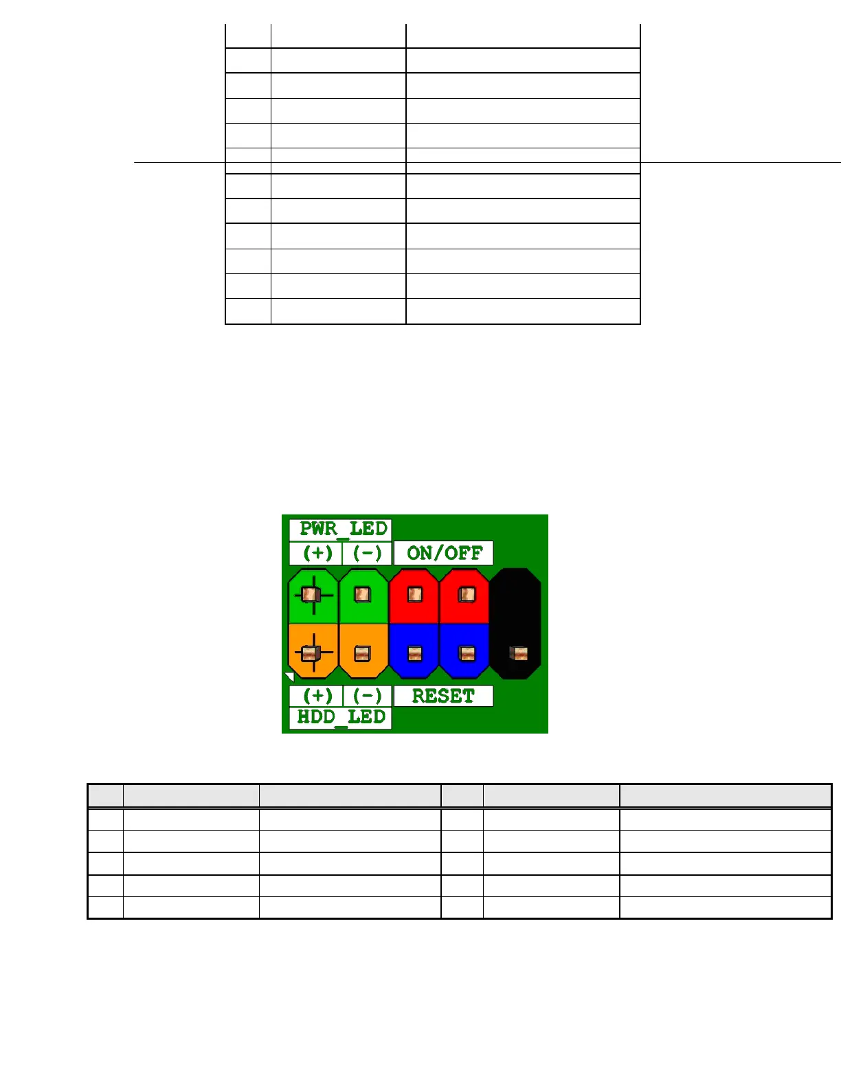
Front panel main header
F i gu re 2 F ron t pa n e l ma i n h e a de r pi n -ou t
Pin
Signal Name
Description
Pin
Signal Name
Description
1
HDD_POWER_LED
Pull-up resistor (750 ) to +5V
2
POWER_LED_MAIN
[Out] Front panel LED (main color)
3
HDD_LED#
[Out] Hard disk activity LED
4
POWER_LED_ALT
[Out] Front panel LED (alt color)
5
GROUND
Ground
6
POWER_SWITCH#
[In] Power switch
7
RESET_SWITCH#
[In] Reset switch
8
GROUND
Ground
9
+5V_DC
Power
10
KEY
No pin
T
A B L E
2
F
R O N T PA N E L M A I N H E A D E R S I G N A L S