EasyManua.ls Logo

Mitsubishi Electric A800 Series User Manual

Mitsubishi Electric A800 Series
154 pages
Go to English
To Next Page IconTo Next Page
Page #1 background imageLoading...
Page #1 background image
800
INSTRUCTION MANUAL (STARTUP) (ENGLISH)
使用手册 ( 导入篇 )( 中文 )
取扱説明書(導入編)(日本語)
HEAD OFFICE: TOKYO BUILDING 2-7-3, MARUNOUCHI, CHIYODA-KU, TOKYO 100-8310, JAPAN
INVERTER
A800 FR-A840M INSTRUCTION MANUAL (STARTUP)
A
A800
FR-A840M-03630(160K)04540(200K)
このたびは、三菱電機汎用インバータをご採用いただき、誠にありがとうございます。
本書と同梱CD-ROM内の情報は、ご使用いただく場合の取扱い、留意点について述べてあります
機器の知識、安全の情報そして注意事項のすべてについて習熟してからご使用ください。
なお、本書と同梱CD-ROMは、ご使用になるお客様の手元に届くようご配慮をお願いいたします
Thank you for choosing this Mitsubishi Electric Inverter.
This Instruction Manual (Startup) and the enclosed CD-ROM give handling information and precautions for use of
this product.
Do not use this product until you have a full knowledge of the equipment, safety information and instructions.
Please forward this Instruction Manual (Startup) and the enclosed CD-ROM to the end user.
非常感谢您选择三菱电机通用变频器。
本使用手册(导入篇)与附带CD-ROM内的内容,包含变频器使用时的操作说明和注意事项。
请在熟悉机器的知识,安全信息以及全部有关注意事项以后使用
请将本使用手册(导入篇)与附带CD-ROM送至使用本产品的客户手中为盼。
三菱電機 汎用 インバータ
INVERTER
断りなしに仕様を変更することがありますのでご了承くださ
Specifications subject to change without notice.
IB(名)-0600932-A(2008)MEEPrintedinJapan

Table of Contents

Question and Answer IconNeed help?

Do you have a question about the Mitsubishi Electric A800 Series and is the answer not in the manual?

Mitsubishi Electric A800 Series Specifications

General IconGeneral
BrandMitsubishi Electric
ModelA800 Series
CategoryInverter
LanguageEnglish

Summary

Safety Instructions and Precautions

General Safety Warnings

Covers handling, electric shock, fire, and injury prevention guidelines.

Installation and Transportation Precautions

Details precautions for transportation and handling during installation.

Environmental Installation Precautions

Inverter Model Identification

Inverter Model Details

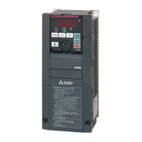
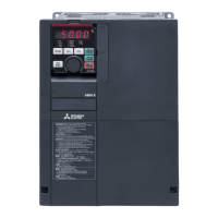
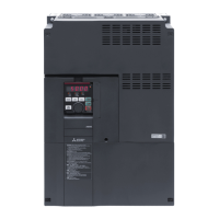
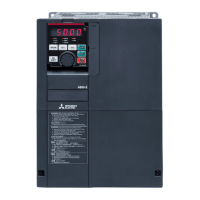
Identifies inverter model naming conventions and specifications.

Component Identification Symbols

Details symbols and descriptions for model identification.

Installing Communication Options

Inverter Component Names

RS-485 Model Component Names

Lists and describes the various components for the RS-485 model.

Ethernet Model Component Names

Installation Environment and Placement

Inverter Placement and Clearances

Specifies required clearances for inverter installation and cooling.

Installation Environment Conditions

Lists acceptable operating conditions for temperature, humidity, and atmosphere.

Peripheral Devices Overview

Inverter and Peripheral Device Diagrams

Shows diagrams of the inverter and its associated peripheral devices.

Peripheral Device Selection Guide

Guide for selecting peripheral devices like circuit breakers and contactors.

Magnetic Contactor Selection

Inverter Panel and Cover Removal/Installation

Operation Panel Removal/Reinstallation

Step-by-step guide for removing and reinstalling the operation panel.

Terminal Cover Removal/Reinstallation

Instructions for removing and reinstalling main circuit terminal covers.

Front Cover Removal/Reinstallation

Inverter Heat Generation

Amount of Heat Generated by Inverter

Table showing the amount of heat generated by the inverter unit.

Wiring Diagrams: FM Type

FM Type Terminal Connection Diagrams

Illustrates terminal connections for FM type inverters.

CA Type Terminal Connection Diagrams

FM Type (Ethernet Model) Terminal Connection Diagrams

CA Type (Ethernet Model) Terminal Connection Diagrams

Main Circuit Wiring

Main Circuit Terminal Layout

Shows the physical layout of the main circuit terminals.

Main Circuit Wiring Method

Details the procedure for wiring the main circuit terminals.

Recommended Cables and Wiring Length

Control Circuit Wiring

Control Circuit Terminal Wiring Precautions

Explains wiring precautions for control circuit terminals.

Stand-Alone Option Unit Connections

Brake Resistor Connection

Instructions for connecting an external brake resistor.

Brake Unit (FR-BU2) Connection

Instructions for connecting the FR-BU2 brake unit.

High Power Factor Converter (FR-HC2) Connection

Power Regeneration Converter (MT-RC) Connection

Basic Operation: Operation Panel

Operation Panel (FR-DU08) Overview

Explains the functions of the operation panel buttons and display.

Operation Mode and Frequency Setting

Parameter Settings and Protective Functions

Parameter Settings for Regeneration

Covers parameters related to regenerative function selection and brake duty.

PWM Frequency Automatic Switchover

Explains automatic reduction of PWM frequency for heavy load.

Instantaneous Power Failure Protection

Explains the E.IPF protective function for instantaneous power failures.

Failsafe Systems

Inverter Status Output Interlock Methods

Describes interlock methods using inverter status signals for failsafe.

Backup Method Outside the Inverter

Discusses failsafe methods independent of the inverter's internal state.

Inverter Use Precautions

Electrical Bearing Corrosion Prevention

Discusses measures to prevent electrical corrosion of motor bearings.

Inverter Output Side Precautions

Warns against connecting specific devices to the inverter output side.

Power Supply Harmonics

Power Supply Harmonics Explanation

Explains how inverters generate power supply harmonics and countermeasures.

Harmonic Suppression Guidelines in Japan

Part Replacement: Cooling Fan

Cooling Fan Removal Procedure

Step-by-step guide for removing the cooling fan.

Cooling Fan Installation

Specifications: Inverter Rating

Inverter Rating Details

Provides detailed specifications for inverter ratings and performance.

Outline Dimension Drawings

Appendix: Model Differences and Compliance

Differences with FR-A840

Highlights key differences between FR-A840M and FR-A840 models.

EU Directives Compliance

Instructions for compliance with EMC and Low Voltage Directives.

UL/cUL Compliance

Motor Overload Protection

Appendix: EAC and Hazardous Substances

EAC Marking Instructions

Guidelines for EAC marking and product distribution in the CU area.

Restricted Hazardous Substances

Information on the restriction of hazardous substances in electronic products.

Enclosed CD-ROM Information

CD-ROM Contents and Usage

Describes the contents of the CD-ROM and how to use it.

CD-ROM System Requirements

Lists the system requirements for accessing the CD-ROM manuals.

Contact Information and Revisions

Mitsubishi Electric Representatives

Lists contact information for representatives in various regions.

Revisions

Information regarding manual revisions and version history.

Inverter Parts Life Display

Life Alarm Status Display

Monitors the life status of internal components like capacitors and fans.

Relay Contact Life Display

Displays the deterioration level of relay contacts.

Communication Options and DriveControl

DriveControl Writing Restriction Selection

Settings to restrict DriveControl parameter changes via communication.

Inverter Monitor Items

Details additional inverter monitor items available for display.

Related product manuals