• Comparing the Low Pressure Sensor Measurement and Gauge Pressure
By configuring the digital display setting switch (SW1) as shown in the figure below, the pressure as measured by the low pressure
sensor appears on the LED1 on the control board.
(1) While the outdoor unit is stopped, compare the gauge pressure and the pressure displayed on self-diagnosis LED1, 2.
1) When the gauge pressure is between 0 and 0.098 MPaG [14 PSIG], internal pressure is caused due to gas leak.
2) When the pressure displayed on self-diagnosis LED1, 2 is between 0 and 0.098 MPaG [14 PSIG], the connector may be defective or
be disconnected. Check the connector and go to (4).
3)
4)
If other than 1), 2) or 3), compare the pressures while the sensor is running. Go to (2).
(2) Compare the gauge pressure and the pressure displayed on self-diagnosis LED1, 2 after 15 minutes have passed since
the start of operation. (Com
pare them by MPaG [PSIG] unit.)
1) When the difference between both pressures is within 0.2 MPaG [29 PSIG ], both the low pressure sensor and the control board are normal.
2) When the difference between both pressures exceeds 0.2 MPaG [29 PSIG], the low pressure sensor has a problem. (performance dete-
rioration)
3) When the pressure displayed on the self-diagnosis LED1, 2 does not change, the low pressure sensor has a problem.
(3) Remove the low pressure sensor from the control board to check the pressure with the self-diagnosis LED1, 2 display.
1) When the pressure displayed on the self-diagnosis LED1,2 is between 0 and 0.098 MPaG [14 PSIG], the low pressure sensor has a
problem.
2) When the pressure displayed on self-diagnosis LED1, 2 is approximately 1.7 MPaG [247 PSIG], the control board has a problem.
(4) Remove the low pressure sensor from the control board, and short-circuit between the pin 2 and pin 3 connectors
(63LS) to check the pressure with t
he self-diagnosis LED1, 2.
1) When the pressure displayed on the self-diagnosis LED1, 2 exceeds 1.7 MPaG [247 PSIG], the low pressure sensor has a problem.
2) If other than 1), the control board has a problem.
(5) Remove the high pressure sensor (63HS) from the control board, and insert it into the connector for the low pres-
sure sensor (63LS) to check the pressure with the self-diagnosis LED1, 2.
1) When the pressure displayed on the self-diagnosis LED1, 2 exceeds 1.7 MPaG [247 PSIG], the control board has a problem.
2) If other than 1), go to (2).
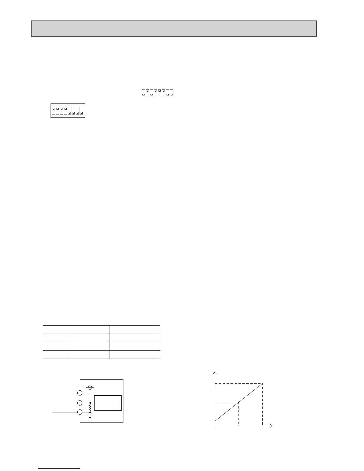
• Low Pressure Sensor Configuration (63LS)
The low pressure sensor consists of the circuit shown in the figure below. If 5 V DC is applied between the red and the black
wires, voltage corresponding to the pressure between the white and the black wires will be output, and the value of this voltage
will be converted by the microcomputer. The output voltage is 0.173 V per 0.098 MPaG [14 PSIG].
The pressure sensor on the body side is designed to connect to the connector. The connector pin number on the body side
is different from that on the control board side.
SW1
ON
1
2 3 456 7 8
ON
1
2 3 456 7 8
The figure at left shows that the switches 1 through 4 are set to ON and 5 through 8 are set to OFF.
Body side Control board side
Vcc Pin 1 Pin 3
Vout Pin 2 Pin 2
GND Pin 3 Pin 1
Note:
3
2
1
RD
WH
BK
SENSOR
5 V DC
GND
63LS
Vout
MICRO
PROCESSOR
3–1 : 5 V (DC)
2–1 : Output Vout (DC)
OUTDOOR MULTI CONTROLLER
CIRCUIT BOARD
Pressure: 0–1.7 MPaG [247 PSIG]
Vout: 0.5–3.5 V
0.173 V/0.098 MPaG [14 PSIG]
<LOW PRESSURE SENSOR>
When the outdoor temperature is 30°C [86°F] or less, and the pressure displayed on self-diagnosis LED1, 2 exceeds 1.7 MPaG
[247 PSIG], go to (3).
When the outdoor temperature exceeds 30°C [86°F], and the pressure displayed on self-diagnosis LED1, 2 exceeds 1.7 MPaG
[247 PSIG], go to (5).
0.850 1.7
123 247
0.5
2.0
3.5
Vout (V)
PRESSURE
(MPaG)
(PSIG)
 Loading...