3
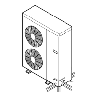
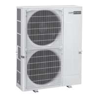
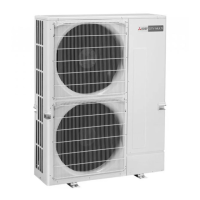
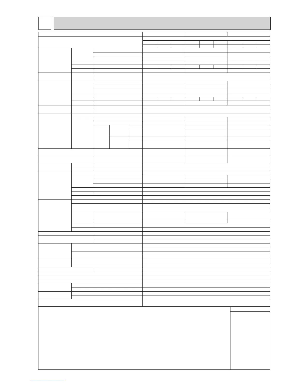
SPECIFICATIONS
Model
PUMY-SP112VKM(R1).TH(-BS) PUMY-SP125VKM(R1).TH(-BS) PUMY-SP140VKM(R1).TH(-BS)
Powersource 1-phase220-230-240V,50Hz;1-phase220V,60Hz
220 230 240 220 230 240 220 230 240
50/60 50 50 50/60 50 50 50/60 50 50
Coolingcapacity
(Nominal)
kW
*1
12.5 14.0 15.5
kcal/h
*1
10,750 12,040 13,330
BTU/h
*1
42,650 47,768 52,886
Powerinput kW
3.10 3.84 4.70
Currentinput A 14.38 13.75 13.18 17.81 17.04 16.33 21.80 20.85 19.98
COP kW/kW 4.03 3.65 3.30
Temp.rangeofcooling Indoortemp. W.B.
15 to 24°C
Outdoortemp. D.B. -5 to 52°C
*3,*4
Heatingcapacity
(Nominal)
kW
*2
14.0 16.0 16.5
kcal/h
*2
12,040 13,760 14,190
BTU/h
*2
47,768 54,592 56,298
Powerinput kW 3.17 3.90 4.02
Currentinput A 14.70 14.06 13.48 18.09 17.30 16.58 18.65 17.83 17.09
COP kW/kW
4.42 4.10 4.10
Temp.rangeofheating Indoortemp. D.B. 15 to 27°C
Outdoortemp. W.B. -20 to 15°C
Indoor unit
connectable
Totalcapacity 50to130%ofoutdoorunitcapacity
Model/
Quantity
City multi 15-140/9 15-140/10 15-140/12
Branchbox 15-100/8 15-100/8 15-100/8
"Mixed
system"
Branchbox
1 unit
City multi
15-140/5 15-140/5 15-140/5
Branch
box
15-100/5 15-100/5 15-100/5
Branchbox
2 units
City multi
15-140/3 or 2
*7
15-140/3 15-140/3
Branch
box
15-100/7 or 8
*7
15-100/8 15-100/8
Soundpressurelevel
(measured in anechoic room)
dB <A>
52/54 53/56 54/56
Powerpressurelevel
(measured in anechoic room)
dB <A>
72/74 73/76 74/76
Refrigerantpiping
diameter
Liquidpipe mm (inch) 9.52(3/8)
Gaspipe mm (inch) 15.88 (5/8)
FAN
*2
Type×Quantity
PropellerFan×1
Airowrate m³/min 77 83 83
L/s
1283 1383 1383
cfm 2719 2931 2931
Control, Driving mechanism DC control
Motoroutput kW 0.20 × 1
Externalstaticpress. 0
Compressor Type×Quantity Twinrotaryhermeticcompressor×1
Manufacturer
MitsubishiElectricCorporation
Starting method Inverter
Capacitycontrol
% Cooling 26 to 100
Heating 20 to 100
Cooling 24 to 100
Heating 18 to 100
Cooling 21 to 100
Heating 17 to 100
Motoroutput kW 3.1 3.5 3.7
Case heater kW
0
Lubricant FV50S (1.4litter)
Externalnish GalvanizedSteelSheetMunsellNo.3Y7.8/1.1
ExternaldimensionH×W×D
mm 981×1,050×330(+40)
inch 38-5/8 × 41-3/8 × 13 (+1-37/64)
Protection devices Highpressureprotection
HighpressureSwitch
Inverter circuit (COMP./FAN) Overcurrent detection, Overheat detection(Heat sink thermistor)
Compressor Compressorthermistor,Overcurrentdetection
Fan motor Overheating,Voltageprotection
Refrigerant Type×originalcharge R410A 3.5 kg
Control Electronicexpansionvalve
Netweight kg (lb) 93(205)
*8
Heatexchanger CrossFinandCoppertube
HIC circuit (HIC: Heat Inter-Changer) HIC circuit
Defrosting method Reversed refrigerant circuit
Drawing External
RK01B171
Wiring BH79J995
Standard attachment Document Installation Manual
Accessory Groundedleadwire×2
Optionalparts Joint:CMY-Y62-G-E
Header: CMY-Y64/68-G-E
Remarks *1 Nominal cooling conditions *2 Nominal heating conditions Unit converter
Indoor:
Outdoor:
Pipelength:
Level difference:
27°CD.B./19°CW.B.[81°FD.B/66°FW.B.]
35°CD.B.[95°FD.B.]
7.5m[24-9/16ft]
0m[0ft]
20°CD.B.[68°FD.B.]
7°CDB/6°CW.B.[45°FD.B./43°FW.B.]
7.5m[24-9/16ft]
0m[0ft]
kcal/h=kW×860
BTU/h=kW×3,412
cfm = m³/min × 35.31
lb = kg/0.4536
Abovespecicationdatais
subject to rounding variation.
*3 10 to 52
°C(D.B)
:,whenconnectingfollowingmodels:PKFY-P15/20/25VBM,PFFY-P20/25/32VLE(R)M,PFFY-P20/25/32VKM,and
Mseries,Sseries,andPseriestypeindoorunitwithbranchbox,Mseriestypeindoorunitwithconnectionkit.
*4
−15to52
°C(D.B)
:,whenusinganoptionalairprotectguide[PAC-SH95AG-E].However,thisconditiondoesnotapplytotheindoorunitlisted
in *3.
*5 UptoP100whenconnectingviabranchbox.
*6 Upto11unitswhenconnectingvia2branchboxes.
*7
Whenconnecting7indoorunitsviabranchbox,connectablecitymultiindoorunitsare3;connecting8indoorunitsviabranchbox,connectablecitymultiindoorunitsare2.
*8 94(207),forPUMY-SP112/125/140VKM(R1).TH-BS.
Notes :1. Nominal conditions *1, *2 are subject to ISO 15042.
2.Duetocontinuingimprovement,abovespecicationsmaybesubjecttochangewithoutnotice.
 Loading...