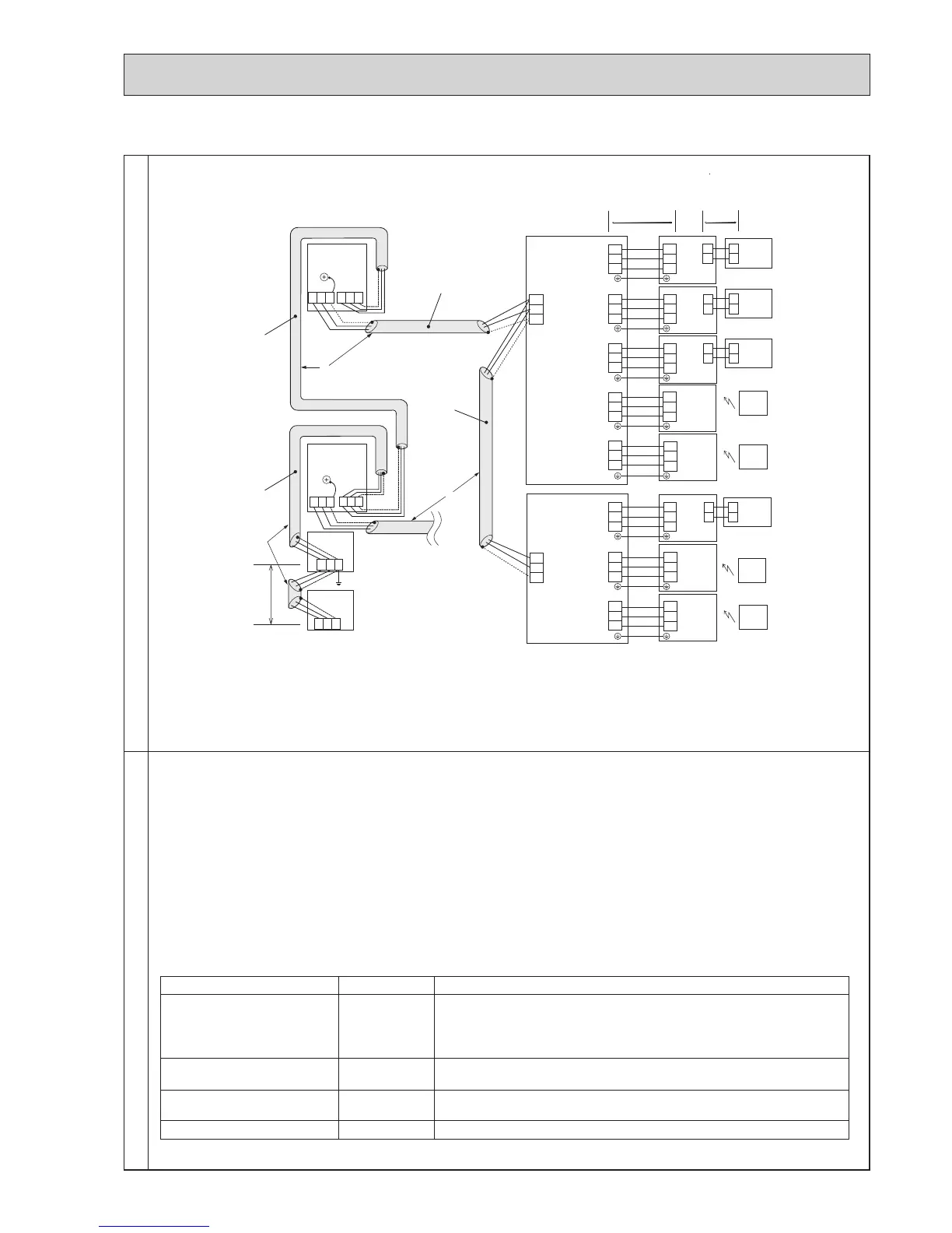
E.ExampleofasystemusingBranchBoxandA-Controlindoorunit
ExamplesofTransmissionCableWiringWiringMethodAddressSettings
a.Alwaysuseshieldedwirewhenmakingconnectionsbetweentheoutdoorunit(OC)andtheBranchBox,aswellfor
allOC-OCwiringintervals.
b.UsefeedwiringtoconnectterminalsM1andM2andthegroundterminalonthetransmissioncableterminalblock(TB3)
of each outdoor unit (OC) to terminals M1 and M2 on the terminal S on the transmission cable terminal block (TB5)
oftheBranchBox.
c. Connect terminals 1 and 2 on the transmission cable terminal block (TB5/TB15) of the A-control indoor unit (A-IC), to
the terminal block on the MA remote controller (MA-RC).
d.ConnecttogetherterminalsM1,M2andterminalSontheterminalblockforcentralizedcontrol(TB7)fortheoutdoor
unit (OC).
e.DONOTchangethejumperconnectorCN41onoutdoormulticontrollercircuitboard.
f.TheearthprocessingofSterminalforthecentralizedcontrolterminalblock(TB7)isunnecessary.Connectthetermi-
nalSonthepowersupplyunittotheearth.
g.Settheaddresssettingswitchasfollows.
Unit Range Setting Method
A-IC 01 to 50
AccordingtothesetaddressofconnectedBranchBox,settheA-ICaddresses
sequentiallybySW1onBranchBox.
(Forexample,whensettingtheBranchBoxaddressto01,A-ICaddressesset
02,03,04, and 05. )
BranchBox 01 to 50
Useanumberwithintherange1–50,butitshouldnotmakethehighest
addressofconnectedA-ICexceed50.
Outdoor Unit 51 to 100
UsethesmallestaddressofalltheBranchBoxplus50.
Theaddressautomaticallybecomes“100”ifitissetas“01–50”.
MA Remote Controller
-
Address setting is not necessary.
A : Shielded wire
( ): Address example
TB7
TB3
(51)
L
3
L1
OC
TB7
(53)
OC
Power Supply
Unit
System
controller
L
4
L5
M1 M2
S
M1 M2
S
S
M1 M2
S
TB3
M1 M2
S
M1 M2
S
M1 M2
TB3A
A-IC
(01)
(02)
(03)
(04)
MA-RC
WL-RC
WL-RC
WL-RC
(05)
(06)
(07)
(08)
S1
S2
S3
TB
S1
S2
TB5/TB15
1
2
A
B
A
B
A
B
A
B
1
2
1
2
1
2
S3
S1
S2
S3
S1
S2
S3
S1
S2
S3
S1
S2
S3
TB
S1
S2
S3
TB
S1
S2
S3
TB
S1
S2
S3
TB3B
S1
S2
S3
TB3C
S1
S2
S3
TB3D
S1
S2
S3
TB3E
S1
S2
S3
TB3A
S1
S2
S3
TB3B
S1
S2
S3
TB3C
S1
S2
S3
M1
M2
S
TB5
M1
M2
S
TB5
L
(01)
(06)
2
Branch Box
A
A
Branch Box
A
A-IC
A-IC
A-IC
A-IC
A-IC
A-IC
A-IC
MA-RC
MA-RC
MA-RC
WL-RC
TB5/TB15
TB5/TB15
TB5/TB15
TB
TB
TB
TB
L
6
m
1
 Loading...