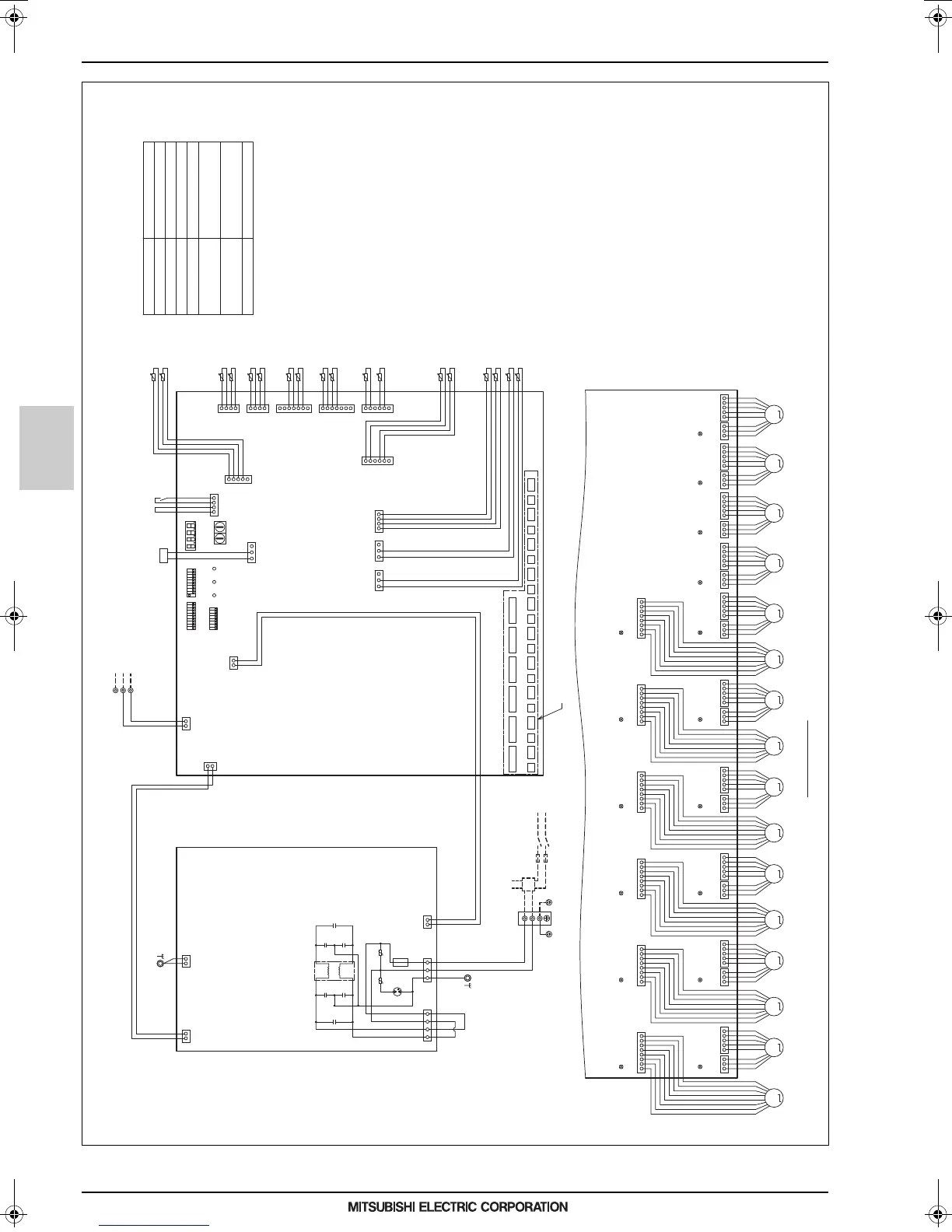
4. ELECTRICAL WIRING DIAGRAMS
Indoor units
MEES17K102
HBC controller
14
EIo-1
NOTE:1.TB02 is transmissionterminal block.
Never connect powerline to it.
2.The initial set valuesof switch on
ControlBoardare asfollows.
SW1:0
SW2:0
Detail of X section
LED1
SW1SW2
SWP2SWP1 SWP3
110
X
DSA001
(Red)
(Green)
(Green)
(Blue)
(Red)
(Blue)
(Red)
(Red)
F001
250VAC
6.3A F
TO NEXT INDOOR UNIT
PULL BOX
FUSE(16A) BREAKER(16A)
POWER SUPPLY
~220V-240V
50Hz/60Hz
Indoor/outdoor
Transmission Line
t
°
t
°
t
°
t
°
t
°
t
°
t
°
t
°
t
°
t
°
t
°
t
°
t
°
t
°
t
°
t
°
t
°
t
°
UU
ZNR001
L001
ZNR002
C004 C006
C003 C005
C002 C007
1
2
32 1
2
1
1
1
11
1
22
2
33
3
2
2
3
3
4
4
11 2
FS
Z
TH31c
TH31m
TH31b
TH31a
TH31f
TH31d
TH31n
TH31p
TH31o
TH31e
TH31h
TH31g
TH31i
TH31j
TH31k
TH31l
TH33
TH32
Control Board
Power Board
1
1
1
1
3
1
1
1
2
2
2
2
1
2
2
2
3
3
3
3
3
3
3
4
4
4
4
4
4
4
5
5
5
5
5
6
6
6
7
7
6
1
355371
S(SHIELD)
TB02
M2
M1
CN005
CNAC
CN002
CN001
CN401
CN103
CN101
CN518
CN507
CN515
CN516
CN514
CN101
CN504(Yellow)
CN506(Blue)
CN505
CN510
CN503(Blue)
CN508(Red)
CN509(Blue)
N
TB01
L
(Red)(Red) (Yellow)(Yellow) (Red) (Red) (Yellow) (Yellow) (Red) (Yellow)(Red) (Yellow)
MM MMMMMMMMMMM MMM
CN202
321
8765432
32145
CN201
1
4321321
87654321
CN203
5
CN204
4321321
87654321
54321321
87654321
CN205
5
CN206
44332211332211554 43 32 21 13 32 21 15 54321321
87654321
54321321
87654321
5
CN801
CN802(Red)
CN803(Yellow) CN806(Yellow)
CN805(Red)
CN804
CN207CN208
CN210 CN209 CN212 CN211
CN214 CN220CN213 CN219
CN216 CN218CN215 CN217
VB3k VB3a VB3bVB3l VB3cVB3m VB3dVB3n VB3eVB3o VB3fVB3p VB3g VB3jVB3h VB3i
LD1:CPU in
operation
LD1:CPU in
operation
LD1:CPU in
operation
LD1:CPU in
operation
LD1:CPU in
operation
LD1:CPU in
operation
LD1:CPU in
operation
LD1:CPU in
operation
LD1:CPU in
operation
LD1:CPU in
operation
LD1:CPU in
operation
LD1:CPU in
operation
LD1:CPU in
operation
LD1:CPU in
operation
LD1:CPU in
operation
LD1:CPU in
operation
(Symbol explanation)
TH31a~p,TH32,TH33
Symbol
Name
Thermister sensor
TB01
Terminal block
(for power source)
TB02
Terminal block
(for Transmission)
Fuse AC250V 6.3A F
F001
VB3a~p
Valve block
Z
FS
Function setting connector
Float switch
SW3
SW4
SW5
123456789 1010
ON
123456789 10
ON
12345678
ON
3.The wirings to TB01 and TB02 shown in
dotted line are field work.
CMB-WM1016V-AB
0000004671.BOOK 14 ページ 2018年3月13日 火曜日 午前11時9分
 Loading...