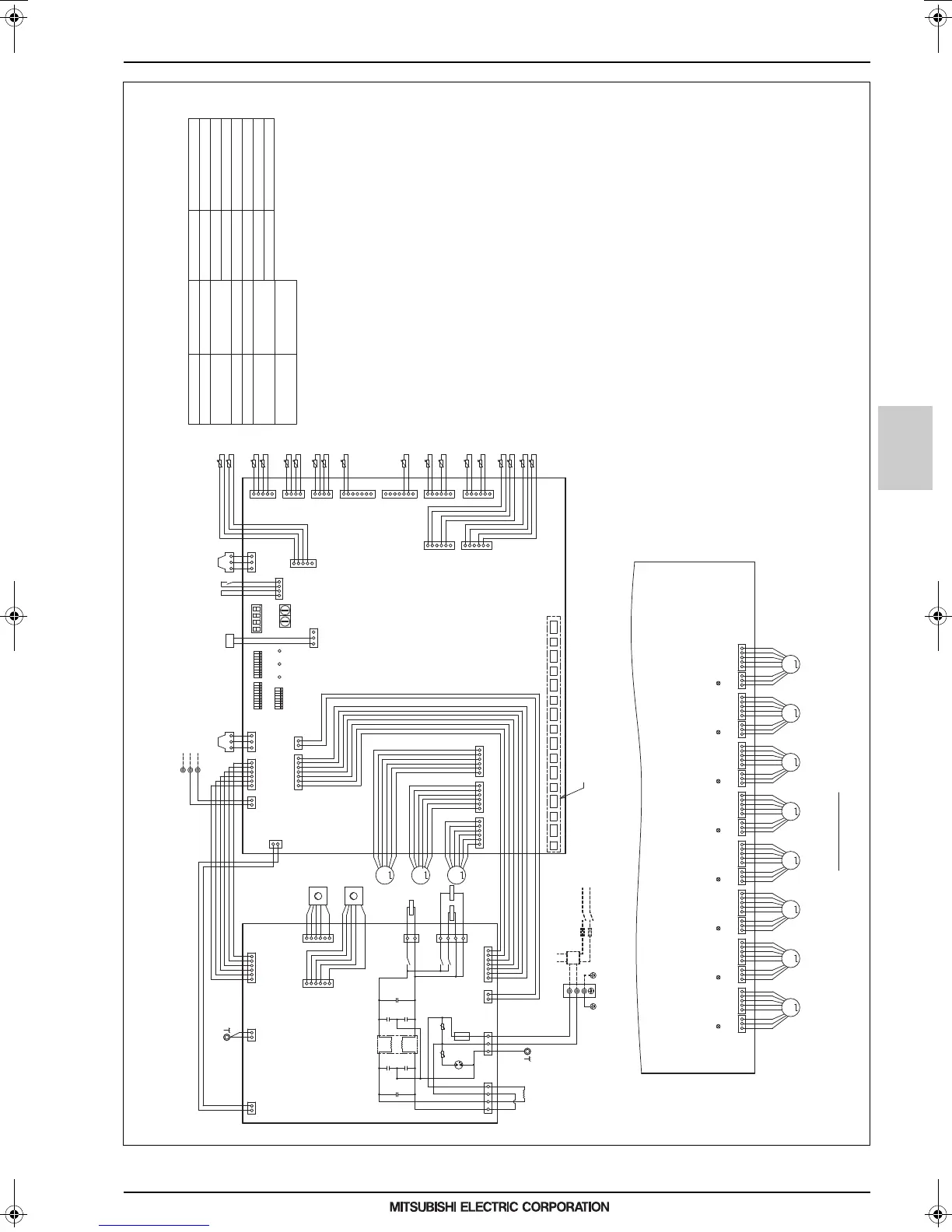
4. ELECTRICAL WIRING DIAGRAMS
Indoor units
MEES17K102
HBC controller
11
EIo-1
4. ELECTRICAL WIRING DIAGRAMS
NOTE:1. TB02 is transmission terminal block.
Never connect power line to it.
2. The initial set values of switch on
Control Board are as follows.
SW1:0
SW2:0
Detail of X section
LED1
SW1SW2
SWP2SWP1 SWP3
1
10
X
DSA001
(Blue)
(Yellow) (Green)
(Red)
(Green)
(Green)
(Blue)
(Blue)
(Yellow)
(Red)
(Red)
(Blue)
(Red)
(Red)
(Red)
(Red)
F001
250VAC
6.3A F
TO NEXT INDOOR UNIT
PULL BOX
FUSE(16A)
BREAKER(16A)
POWER SUPPLY
~220V-240V
50Hz/60Hz
Indoor/outdoor
Transmission Line
t°
t°
t°
t°
t°
t°
t°
t°
t°
t°
t°
t°
t°
t°
t°
t°
t°
t°
M
M
M
UU
X002
X006
X003
ACL
SV1
21S4Mb 21S4Ma
ZNR001
L001
ZNR002
C004 C006
C003 C005
C002 C007
LEV1
LEV2
LEV3
WP1
WP2
1
3
1
7
2
6
3
5
4
4
5
3
6
2
1
2
32 1
7
1
2
1
1 1
1
11 22 33
2 2
2
3 3
34
11 24 45 56 6
PS1PS3
FS
TH12
TH11
TH31c
TH31b
TH31a
TH31f
TH31d
TH13
TH14
TH31e
TH31h
TH31g
TH34
TH35
TH16
TH33
TH15
TH32
666
555
444
333222
111
Control Board
Power Board
1
1
1
1
1
11
1
3
1
1
1
1
2
2
2
2
2
22
2
1
2
2
2
2
3
3
3
3
3
33
3
3
3
3
3
4
4
4
4
4
55
4
4
4
4
4
5
5
5
5
5
77
5
5
5
6
6
6
6
6
7
7
99
6
6
5
3
1
1
355371
S(SHIELD)
TB02
M2
M1
CNLEV1 CNLEV2 CNLEV3
CN005
CNAC
CN002
CN001
CN001
CN002
CN006
CN203
CN204
CN401
CN103
CN101
CN518
CN512CN513
CN201
CN003
CN101
CN003
CN501
CN502(Red)
CN504(Yellow)
CN506(Blue)
CN505
CN510
CN503(Blue)
CN508(Red)
CN509(Blue)
CN511(Red)
N
TB01
L
(Red)(Red) (Yellow)(Yellow) (Red) (Red) (Yellow) (Yellow) (Red) (Red)
MMMMMMMM
CN202
32132145
CN201
4321321
CN203
5
CN204
432132154321321
CN205
5
CN206
43213215432132154321321543213215
CN207CN208
CN210 CN209 CN212 CN211
CN214 CN213
CN216 CN215
VB3a VB3b VB3c VB3d VB3e VB3f VB3g VB3h
LD1:CPU in
operation
LD1:CPU in
operation
LD1:CPU in
operation
LD1:CPU in
operation
LD1:CPU in
operation
LD1:CPU in
operation
LD1:CPU in
operation
LD1:CPU in
operation
(Symbol explanation)
LEV1~3
TH11~16,TH32~35,
TH31a~h
ACL
PS1,PS3
Pressure sensor
Symbol
Name
AC reactor
Thermister sensor
Expansion valve
TB01
Terminal block
(for power source)
TB02
Terminal block
(for Transmission)
Fuse AC250V 6.3A F
F001
Solenoid valve
SV1
21S4Ma,21S4Mb
4 way valve
WP1,WP2
Pump
Name
Symbol
VB3a~h
Valve block
FS
Float switch
(Blue)
123
Z
CN514
Z
Function setting connector
SW3
SW4
SW5
123456789
ON
10 12345678910
ON
12345678
ON
3. The wirings to TB01 and TB02 shown in
dotted line are field work.
CMB-WM108V-AA
0000004671.BOOK 11 ページ 2018年3月13日 火曜日 午前11時9分
 Loading...