EasyManua.ls Logo

Mitsubishi Electric E1071 - User Manual

Mitsubishi Electric E1071
20 pages
Print Icon
To Next Page IconTo Next Page
Loading...
MITSUBISHI ELECTRIC
E1071
Installation manual
MA00777A 2006-04
English
Question and Answer IconNeed help?

Do you have a question about the Mitsubishi Electric E1071 and is the answer not in the manual?

Summary

Foreword

Safety Precautions

UL Installation

Power, input/output wiring must comply with Class 1, Division 2 wiring methods.

General Safety

Only qualified personnel may install/operate; plane surface installation; avoid specific environmental conditions.

Usage Guidelines

Keep clean, do not control safety functions, avoid excessive force on keys/display.

Service and Maintenance

Repairs by qualified personnel; disconnect power for cleaning; use mild detergent; proper battery replacement.

Dismantling and Scrapping

Recycle according to local regulations; identify hazardous components.

Installation

Space Requirements

Details installation plate thickness and required clearances around the operator terminal.

Installation Process

Outlines steps for unpacking, checking, panel cut-out, and securing the unit.

Mode Switches

Mode switches must be OFF during operation; should only be touched by qualified personnel.

Controller Connections

Refers to driver help file for cable information when connecting to the controller.

Other Connections and Peripherals

Cables and peripherals must suit the application; caution regarding compact flash card removal.

Technical Data

Chemical Resistance

Metal Casing Resistance

Powder-coated aluminum casing withstands exposure to specific chemicals for up to 24 hours.

Touch Screen and Overlay Resistance

Covers Autotex F250 overlay and its solvent resistance properties.

Touch Screen Surface Resistance

Lists solvents the touch screen surface can withstand without visible change and their time limits.

Autoflex EB Film Resistance

Recommends Autoflex EB film and details its solvent resistance and limitations.

Operator Terminal Drawings

Communication Ports Overview

Illustrates and details pin assignments for RS-232, RS-422/485, USB, and Ethernet ports.

E1071 Outline Dimensions

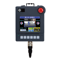
Provides dimensional drawings and port layout for the E1071 operator terminal.

Overview

The E1000 series operator terminal is a human-machine interface designed to facilitate communication and control in automation systems. This device is engineered to meet the demands of modern industrial environments, offering a robust set of built-in functions for displaying information, controlling processes, and managing data.

Function Description

The primary function of the E1000 operator terminal is to provide an intuitive interface for interacting with various automation equipment, collectively referred to as "the controller" in this manual. This includes Programmable Logic Controllers (PLCs), servos, and drives. The terminal supports a wide array of functionalities, making it a versatile tool for monitoring and controlling industrial processes.

Key functions include:

  • Text Display and Control: The terminal can display textual information, allowing operators to view status messages, instructions, and data. It also provides means for controlling text-based inputs and outputs.
  • Dynamic Indication: This feature enables the display of real-time, changing data, such as sensor readings, process values, or machine states, providing immediate feedback to the operator.
  • Time Channels: The integration of time channels allows for scheduling and time-based control of operations, which can be critical for sequential processes or timed events.
  • Alarm Handling: The terminal is equipped with alarm management capabilities, alerting operators to critical events or deviations from normal operating parameters. This helps in prompt identification and resolution of issues, enhancing operational safety and efficiency.
  • Recipe Handling: For applications requiring different sets of parameters or configurations, the recipe handling function allows operators to store, select, and apply predefined recipes, streamlining production changes and ensuring consistency.

The E1000 terminal operates in an object-oriented manner, which contributes to its ease of understanding and use. Configuration of the terminal is performed on a personal computer using the dedicated E-Designer configuration tool. Once a project is created and configured, it is transferred and stored within the operator terminal, ready for deployment. The terminal's ability to connect to various types of automation equipment underscores its role as a central point of interaction in an automated system.

Usage Features

The E1000 operator terminal is designed for stationary installation on a plane surface, ensuring stability and reliability in industrial settings. Its design considers various environmental factors to ensure optimal performance and safety.

Important usage considerations include:

  • Installation Environment: The terminal is intended for environments free from high explosive risks, strong magnetic fields, direct sunlight, and large, sudden temperature changes. These conditions are crucial for maintaining the integrity and functionality of the device, particularly its LCD display.
  • User Interface: The terminal features a touch screen interface, allowing for direct interaction with the displayed content. The touch screen is designed for durability, supporting millions of finger touch operations. Users should avoid using excessive force or sharp objects when interacting with the display or keys to prevent damage.
  • Connectivity: The E1000 offers multiple communication ports, including RS422/RS485, RS232C, Ethernet, and USB, enabling flexible integration with a wide range of controllers and peripheral equipment. Shielded communication cables are recommended to ensure reliable data transmission and minimize interference.
  • Power Supply: The terminal operates on a +24V DC power supply. It is essential to ensure that the voltage and polarity of the power source are correct to prevent damage to the unit. The power supply must conform to relevant safety standards (SELV or PELV according to IEC 950 or IEC 742 for CE, and Class II power supplies for UL).
  • Compact Flash Card Support: The terminal includes a CF-slot for compact flash cards (Type I and II), which can be used for data storage or project transfer. Users should exercise caution and avoid removing the card when the busy indicator is illuminated to prevent data corruption.
  • Mode Switches: The terminal is equipped with mode switches, which must be in the OFF position during normal operation. These switches should only be accessed and adjusted by qualified personnel.
  • EMC Compliance: The E1000 conforms to the essential protection requirements of the EMC directive 89/336/EEC, having been tested for noise emission and immunity according to EN61000-6-4 and EN61000-6-2 standards.

Maintenance Features

Proper maintenance is crucial for the longevity and reliable operation of the E1000 operator terminal. The manual outlines specific guidelines for service, cleaning, and eventual dismantling.

Key maintenance aspects include:

  • Qualified Personnel: All repairs and significant maintenance operations should only be carried out by qualified personnel to ensure safety and proper functioning of the device.
  • Electrical Disconnection: Before performing any cleaning or maintenance tasks, the equipment must be disconnected from the electrical supply to prevent electrical shock or damage.
  • Cleaning: The display and the surrounding front cover should be cleaned with a soft cloth and a mild detergent. Harsh chemicals or abrasive materials should be avoided to prevent scratching or damage to the screen and casing.
  • Battery Replacement: The terminal contains a real-time clock battery. Incorrect replacement of this battery can lead to an explosion. Only batteries recommended by the supplier should be used for replacement. The minimum life of the real-time clock battery is 3 years at 25 °C.
  • Environmental Acclimatization: If the terminal has been stored in temperatures outside its operating range, it must be brought to ambient temperature before startup. If condensation forms, the terminal must be completely dry before connecting it to the power outlet.
  • Chemical Resistance: The metal casing, touch screen, and overlay materials (Autotex F250 and Autoflex EB) are designed to withstand exposure to various chemicals for specific durations without visible change. This information is critical for cleaning and for assessing suitability in environments where chemical exposure is possible. However, certain concentrated acids, caustic solutions, and high-pressure steam are not recommended.
  • Dismantling and Scrapping: At the end of its life cycle, the operator terminal or its parts should be recycled according to local regulations. It is important to note that certain components, such as the lithium battery, electrolytic capacitors, and the display, contain substances that may be hazardous to health and the environment and require special handling during disposal.
  • Supplier Responsibility: The supplier is not responsible for modified, altered, or reconstructed equipment. Only parts and accessories manufactured according to the supplier's specifications should be used for repairs or replacements.

Mitsubishi Electric E1071 Specifications

General IconGeneral
Screen Size10.4 inches
Resolution640 x 480 pixels
Touch PanelResistive
Input Voltage24 VDC
Display DeviceTFT LCD
Communication InterfaceRS-232, RS-422/485
Protection RatingIP65
DisplayTFT LCD
InterfaceRS-232C, RS-422/485
Operating Temperature0°C to 50°C
Storage Temperature-20°C to 60°C
Weight2.5 kg

Related product manuals