Do you have a question about the Mitsubishi Electric E1061 and is the answer not in the manual?
Safety requirements for UL and cUL installations, including environmental conditions and component substitution.
General safety precautions for operating and handling the operator panel.
Safety guidelines to follow during the installation process.
Safety measures and precautions to observe while using the operator panel.
Safety procedures for servicing and maintaining the operator panel.
Guidelines for safe dismantling and environmentally responsible scrapping of the panel.
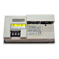
Details on the physical space and mounting dimensions required for installation.
Step-by-step instructions for the installation procedure.
Explanation of the function and setting of mode switches.
Instructions for connecting the operator panel to the controller.
Information on connecting other peripherals and accessories.
Resistance of the metal casing to various chemicals.
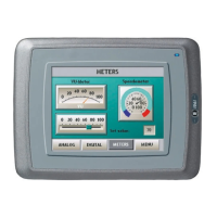
Information about the touch screen and overlay materials.
Solvent resistance properties of the Autotex overlay material.
Resistance of the touch screen surface to solvents.
Details on the Autoflex EB touch display protection film.
Diagrams and pin assignments for various communication ports (RS-232, RS-422/485, USB, Ethernet).
Dimensional drawings and layout of the E1061/E1063 operator panels.
Recommendations for proper grounding of the operator panel for optimal performance and safety.
Guidance on making Ethernet connections and managing shielding.
Methods for improving Electromagnetic Compatibility (EMC) protection.
Factors affecting ambient temperature within the device cabinet and panel operation.
Safety considerations related to power supply and isolation.
Explanation of galvanic isolation and its importance for communication.
Guidelines for cabling and termination specific to RS485 communication.
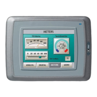
This document provides an installation manual for the Mitsubishi Electric E1061 and E1063 operator panels, part of the E1000 series. It covers safety precautions, installation procedures, technical data, chemical resistance, operator panel drawings, and additional installation tips.
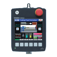
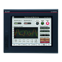
The E1000 series operator panels are designed for human-machine communication, offering built-in functions such as text display and control, dynamic indication, time channels, alarm handling, and recipe management. These panels operate in an object-oriented manner, making them intuitive to understand and use. Configuration is performed on a PC using a dedicated configuration tool, and the project can then be transferred and stored directly on the operator panel. The panels can connect to various automation equipment, including PLCs, servos, and drives, with "the controller" referring to the connected equipment.
The operator panel is designed for stationary installation on a flat surface, requiring specific environmental conditions: no high explosive risks, no strong magnetic fields, no direct sunlight, and no large, sudden temperature changes. The installation process involves unpacking, checking for damage, and then securing the panel using provided brackets and screws. It is crucial to ensure that the operator panel and the controller system share the same electrical grounding to prevent communication errors. Only shielded communication cables should be used, and high voltage cables must be separated from signal and supply cables. Before starting the panel, it must be brought to ambient temperature, and any condensation must be allowed to dry. The voltage and polarity of the power source must be correct.
The mode switches on the panel must always be in the OFF position during normal operation and should only be adjusted by qualified personnel. For connecting to controllers, users should refer to the help file for the specific driver. All peripheral equipment and accessories must be suitable for the application and its environment.
The touch screen surface is made of polyester on glass, designed for 1 million finger touch operations. The overlay is made of Autotex F157/F207, which offers good solvent resistance to various chemicals for extended periods, but is not suitable for high-pressure steam or long-term direct sunlight exposure. The touch screen surface itself can withstand exposure to certain solvents like acetone, isopropanol, and toluene for specific durations without visible change. For enhanced protection, the Autoflex EB touch display protection film is recommended.
To ensure safe and reliable operation, several maintenance guidelines are provided. The operator panel should be kept clean. Emergency stop and other safety functions should not be controlled from the operator panel. When interacting with the touch screen or keys, excessive force or sharp objects should be avoided.
Only qualified personnel are authorized to perform repairs. Before any cleaning or maintenance, the equipment must be disconnected from the electrical supply. The display and front cover should be cleaned with a soft cloth and mild detergent. Incorrect battery replacement can lead to an explosion, so only batteries recommended by the supplier should be used.
For optimal EMC protection, it is recommended to use original cabling from the supplier, shielded cables for RS232, and twisted pair shielded cabling for RS422 and RS485. Cabling should follow the specifications for the bus type (Ethernet, Profibus, CC-Link, CAN, Device Net). D-sub covers should be shielded, with the shield connected 360° where the cable enters. Shields should ideally be connected at both ends, but for longer distances or differing ground potentials, one end can be connected via a 0.1 µF/250 V plastic capacitor to prevent ground current loops. EMC cable glands or metal cable clamps should be used to connect the shield to the installation plate. 24 V DC and communication cabling should be separated from 230/380 V AC cabling, and if they must cross, they should do so at a 90° angle. Ferrite cores snapped onto shielded or unshielded cabling can help suppress minor disturbances.
Regarding ambient temperature, the maximum specified temperature refers to the temperature inside the device cabinet. If the cabinet is tall or contains heat-generating devices, the internal temperature can be significantly higher. High temperatures reduce the lifespan of electronic components, particularly electrolytic capacitors. Installing a fan, preferably in the cooler area and blowing air towards the operator panel, can help even out temperature and improve cooling. A thermostat can be used to activate the fan only when needed. Reducing background lighting on graphic terminals can also significantly decrease power loss and heat generation.
For safety, if the 24 V DC power supply also feeds other units, caution is advised. The operator panel's insulation does not meet safety requirements for a potential short circuit between 230 V AC and 24 V DC. Therefore, the 24 V feed must be secure (e.g., SELV according to EN 60950 or UL 950). If there is a substantial distance between relay contacts for 24 V DC and 230 V AC, using the same 24 V devices for all feeds is acceptable. Connecting 0 V on the 24 V feed to ground enhances safety, connects transients to ground, and prevents the 24 V feed from reaching a high potential relative to ground due to static electricity.
The operator panel has galvanic isolation against the 24 V DC feed, but not between RS232, RS422/485, and USB communication ports. Only the Ethernet connection has galvanic isolation. When a PC or USB device is connected, the panel's internal 0 V (GND) may connect to the protective ground. If multiple units with 0 V and ground connections are connected to different grounding points, grounding currents can flow through communication cables, potentially causing errors. Using external units for galvanic isolation and improved communication, such as industry-standard insulators, is recommended.
For RS485 bus termination, shielded and twisted pair cables with specific capacitance and area are required. The 0 V reference voltage for communication should be included in the cabling. The shield should be grounded at one end, or via a capacitor for longer distances. Various termination methods exist, and newer panels often have built-in "Fail Safe" termination. If other nodes require pull-up/pull-down, external resistors or specific cables like CAB8 can be used for proper termination.
| Power Supply | 24 VDC |
|---|---|
| Display Type | TFT LCD |
| Backlight | LED |
| Touch Panel | Resistive |
| Communication Interface | Ethernet, RS-232 |
| Memory | Flash memory |
| Protection Rating | IP65 |