C
Carol WallsAug 6, 2025
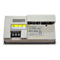
Why is sequence program transfer/monitoring disabled on my Mitsubishi Electric F920GOT-BBD5-K-E?
- GGary YoungAug 7, 2025
If sequence program transfer or monitoring is disabled on your Mitsubishi Electric Touch terminals, it might be because the PLC connection is set to "RS-232C", or the bar code reader or printer is set to valid. To resolve this, set the PLC connection to RS-422, or consider using a model with two built-in RS-232C ports, such as the F943GOT-SBD-H. Alternatively, if the bar code reader or printer settings are the issue, change them in the screen creation software.