EasyManua.ls Logo

Mitsubishi Electric FR-A741 User Manual

Mitsubishi Electric FR-A741
217 pages
To Next Page IconTo Next Page
Page #1 background imageLoading...
Page #1 background image
HEAD OFFICE: TOKYO BUILDING 2-7-3, MARUNOUCHI, CHIYODA-KU, TOKYO 100-8310, JAPAN
FR-A701
INSTRUCTION MANUAL (BASIC)
FR-A721-5.5K to 55K
FR-A741-5.5K to 55K
INVERTER
IB(NA)-0600331ENG-D(0807)MEE Printed in Japan Specifications subject to change without notice.
FR-A701 INVERTER INSTRUCTION MANUAL (BASIC)
D
701
1
2
3
4
5
6
7
CONTENTS
OUTLINE ....................................................................................................... 1
1.1 Product checking and parts identification .........................................................................1
1.2 Inverter and peripheral devices.........................................................................................2
1.3 Method of removal and reinstallation of the front cover....................................................4
1.4 Installation of the inverter and enclosure design ..............................................................6
WIRING........................................................................................................ 12
2.1 Terminal connection diagram......................................................................................... 12
2.2 Main circuit terminal specifications................................................................................. 13
2.3 Control circuit specifications........................................................................................... 20
2.4 Connection of motor with encoder (vector control) ........................................................ 28
PRECAUTIONS FOR USE OF THE INVERTER......................................... 35
3.1 EMC and leakage currents ............................................................................................ 35
3.2 Power-off and magnetic contactor (MC)........................................................................ 41
3.3 Inverter-driven 400V class motor ................................................................................... 42
3.4 Precautions for use of the inverter ................................................................................. 43
3.5 Failsafe of the system which uses the inverter .............................................................. 45
DRIVE THE MOTOR ................................................................................... 47
4.1 Step of operation ............................................................................................................47
4.2 Operation panel (FR-DU07)........................................................................................... 48
4.3 Before operation.............................................................................................................56
4.4 Start/stop from the operation panel (PU operation mode)............................................. 83
4.5 Make a start and stop with terminals (external operation)............................................. 88
4.6 Parameter List ................................................................................................................ 95
TROUBLESHOOTING .............................................................................. 139
5.1 Reset method of protective function ............................................................................ 139
5.2 List of fault or alarm display ......................................................................................... 140
5.3 Causes and corrective actions..................................................................................... 141
5.4 Correspondences between digital and actual characters............................................ 156
5.5 Check and clear of the faults history..................................................................... 157
5.6 Check first when you have troubles............................................................................. 159
PRECAUTIONS FOR MAINTENANCE AND INSPECTION..................... 162
6.1 Inspection item ............................................................................................................. 162
6.2 Measurement of main circuit voltages, currents and powers ...................................... 169
SPECIFICATIONS..................................................................................... 174
7.1 Rating ........................................................................................................................... 174
7.2 Common specifications ................................................................................................ 177
7.3 Outline dimension drawings......................................................................................... 178
7.4 Installation of the heatsink portion outside the enclosure for use................................ 187
Thank you for choosing this Mitsubishi Inverter.
This Instruction Manual is intended for users who "just want to run the inverter".
If you are going to utilize functions and performance, refer to the FR-A701 Series Instruction Manual (applied) [IB-
0600337ENG]. The Instruction Manual (applied) is separately available from where you purchased the inverter or
your Mitsubishi sales representative.
1
2
3
4
5
6
7

Table of Contents

Question and Answer IconNeed help?

Do you have a question about the Mitsubishi Electric FR-A741 and is the answer not in the manual?

Mitsubishi Electric FR-A741 Specifications

General IconGeneral
SeriesFR-A741
Frequency50Hz/60Hz
Cooling MethodForced Air Cooling
Ambient Temperature-10°C to +50°C
Storage Temperature-20°C to +65°C
Frequency Range0.2Hz - 400Hz
Control MethodV/F control, Vector Control
Protection ClassIP20
Overload Capacity150% for 60s
Braking UnitBuilt-in
Protection FunctionsOvercurrent, Overvoltage, Undervoltage, Overheat
CommunicationRS-485
Humidity95% RH or less (non-condensing)
AltitudeUp to 1000 m above sea level
Vibration5.9 m/s²
Rated Output CurrentCorresponds to the power range, refer to the specifications table.

Summary

1 OUTLINE

1.1 Product checking and parts identification

Unpack the inverter and check capacity plates to ensure product agreement and integrity.

1.2 Inverter and peripheral devices

Details essential peripheral devices like MCCBs, MCs, noise filters, and their connection.

1.3 Method of removal and reinstallation of the front cover

Step-by-step instructions for safely removing and reinstalling the operation panel and front cover.

1.4 Installation of the inverter and enclosure design

Guidelines for designing enclosures and installing inverters to ensure optimal performance and reliability.

2 WIRING

2.1 Terminal connection diagram

Provides a comprehensive diagram showing all terminal connections for main and control circuits.

2.2 Main circuit terminal specifications

Details the specifications and functions of the main circuit terminals for AC power input and motor output.

2.2.3 Cables and wiring length

Specifies recommended cable sizes and wiring lengths for optimal performance and voltage drop.

2.3 Control circuit specifications

Describes the functions and specifications of various control circuit terminals for input and output signals.

2.4 Connection of motor with encoder (vector control)

Explains how to connect a motor with an encoder for vector control operation using the FR-A7AP.

3 PRECAUTIONS FOR USE OF THE INVERTER

3.1 EMC and leakage currents

Discusses measures to prevent electromagnetic noise and leakage currents affecting performance.

3.2 Power-off and magnetic contactor (MC)

Recommends using magnetic contactors for safety, maintenance, and preventing automatic restarts.

3.3 Inverter-driven 400V class motor

Advises on measures for 400V class motors to prevent insulation deterioration due to surge voltages.

3.4 Precautions for use of the inverter

Lists important precautions for inverter operation, wiring, and handling to prevent damage or injury.

3.5 Failsafe of the system which uses the inverter

Explains how to implement failsafe measures using inverter status signals and external backups.

4 DRIVE THE MOTOR

4.1 Step of operation

Provides a flowchart for performing basic inverter setup and operation, including commands and settings.

4.2 Operation panel (FR-DU07)

Describes the parts and functions of the FR-DU07 operation panel for monitoring and parameter adjustment.

4.2.3 Operation lock (Press [MODE] for an extended time (2s))

Explains how to lock the operation panel to prevent unauthorized parameter changes or accidental operations.

4.2.4 Monitoring of output current and output voltage

Details how to monitor output current and voltage using the operation panel's SET button.

4.2.8 Parameter clear, all parameter clear

Describes the procedure for clearing individual or all parameters to their initial values.

4.2.9 Parameter copy and parameter verification

Explains how to copy parameters between inverters and verify parameter settings.

4.3 Before operation

Covers essential checks and settings before starting inverter operations, including parameter lists.

4.3.3 When the rated motor frequency is 50Hz (Pr. 3)

Details setting the base frequency (Pr. 3) to 50Hz when the motor is rated for 50Hz to ensure proper torque.

4.3.4 Increase the starting torque (Pr. 0)

Explains how to adjust the Pr. 0 Torque boost parameter to improve starting torque for loads that may not rotate.

4.3.5 Limit the maximum and minimum output frequency (Pr. 1, Pr. 2)

Describes how to set the upper and lower limits for the output frequency to protect the motor and system.

4.3.6 Change acceleration and deceleration time (Pr. 7, Pr. 8)

Explains how to set acceleration and deceleration times to control motor speed changes smoothly.

4.3.7 Selection of the start command and frequency command locations (Pr. 79)

Details how to select the source for start commands and frequency commands (PU, terminals, etc.).

4.3.10 To exhibit the best performance of the motor performance (offline auto tuning) (Pr. 71, Pr. 83, Pr. 84, Pr. 96)

Explains how to perform offline auto tuning to maximize motor performance by measuring constants.

4.3.12 To perform high accuracy/fast response operation (gain adjustment of real sensorless vector control and vector control) (Pr. 818 to Pr. 821, Pr. 880)

Details how to perform gain adjustment for real sensorless vector and vector control for optimal performance.

4.4 Start/stop from the operation panel (PU operation mode)

Explains how to start/stop the inverter and set frequency using the PU operation panel.

4.4.2 Use the setting dial like a potentiometer to perform operation.

Explains how to use the setting dial as a potentiometer to adjust the frequency and operate the inverter.

4.4.3 Use switches to give a start command and a frequency command (multi-speed setting) (Pr. 4 to Pr. 6)

Guides on using external switches for start commands and multi-speed frequency settings with external operation.

4.4.4 Perform frequency setting by analog (voltage input)

Details how to set the frequency using an analog voltage input signal to terminals 2 or 4.

4.4.5 Perform frequency setting by analog (current input)

Explains how to set the frequency using an analog current input signal to terminal 4 for external operation.

4.5 Make a start and stop with terminals (external operation)

Guides on starting and stopping the inverter and setting frequency using external terminals.

4.5.1 Use the set frequency set by the operation panel (Pr. 79 = 3)

Describes how to start/stop the inverter and set frequency using terminals when Pr. 79 is set to 3.

4.5.2 Use switches to give a start command and a frequency command (multi-speed setting) (Pr. 4 to Pr. 6)

Guides on using switches for start commands and multi-speed frequency settings with external operation.

4.5.3 Perform frequency setting by analog (voltage input)

Explains how to set the frequency using an analog voltage input signal to terminals 2 or 4 for external operation.

4.5.4 Change the frequency (60Hz) of the maximum value of potentiometer (at 5V, initial value)

Guides on adjusting the maximum frequency setting for analog voltage input when using a potentiometer.

4.5.5 Perform frequency setting by analog (current input)

Explains how to set the frequency using an analog current input signal to terminal 4 for external operation.

4.6 Parameter List

Provides a categorized list of parameters for various functions, including control modes and settings.

4.6.1 List of parameters classified by purpose of use

A comprehensive list of parameters organized by their intended purpose, aiding in configuration.

4.6.2 Parameter list

Detailed list of parameters with initial values, ranges, and descriptions for easy reference and setting.

5 TROUBLESHOOTING

5.1 Reset method of protective function

Explains how to reset the inverter after a protective function has tripped or an alarm has occurred.

5.2 List of fault or alarm display

Provides a comprehensive list of inverter fault and alarm indications with corresponding causes and references.

5.3 Causes and corrective actions

Details common causes for error messages and provides corrective actions for each.

5.3 Causes and corrective actions

Lists causes and corrective actions for warnings such as OL (Stall Prevention) and PS (PU Stop).

5.3 Causes and corrective actions

Details causes and corrective actions for alarms like FN (Fan Fault) and faults like E.OC1, E.OC2.

5.3 Causes and corrective actions

Lists causes and corrective actions for faults such as E.OC3, E.OV1, E.OV2, E.THT, E.THM.

5.3 Causes and corrective actions

Details causes and corrective actions for faults like E.OV3, E.THT, E.THM.

5.3 Causes and corrective actions

Lists causes and corrective actions for faults like E.FIN, E.IPF, E.UVT, E.ILF.

5.3 Causes and corrective actions

Details causes and corrective actions for faults like E.OLT, E.GF, E.LF, E.OHT, E.PTC.

5.3 Causes and corrective actions

Lists causes and corrective actions for faults like E.OPT, E.OP3, E.1 to E.3, E.PE, E.PE2.

5.3 Causes and corrective actions

Details causes and corrective actions for faults like E.PUE, E.RET, E.6, E.7, E.CPU, E.CTE.

5.3 Causes and corrective actions

Lists causes and corrective actions for faults like E.OS, E.OSD, E.ECT, E.OD.

5.3 Causes and corrective actions

Details causes and corrective actions for faults like E.EP, E.P24, E.CDO, E.IOH, E.SER.

5.3 Causes and corrective actions

Lists causes and corrective actions for faults like E.AIE, E.4, E.8, E.10.

5.5 Check and clear of the faults history

Explains how to check and clear the inverter's faults history displayed on the operation panel.

5.6 Check first when you have troubles

Provides a checklist of common issues and initial checks when the motor or inverter does not operate correctly.

5.6.3 Inverter generates abnormal noise.

Discusses potential causes for abnormal inverter noise and checks to perform.

5.6.4 Motor generates heat abnormally

Lists checks for abnormal motor heating, including fan operation, load, and settings.

5.6.11 Speed varies during operation

Addresses issues where speed varies during operation due to load changes, input signals, or parameter settings.

5.6.12 Operation mode is not changed properly

Provides troubleshooting steps when the inverter's operation mode cannot be changed correctly.

6 PRECAUTIONS FOR MAINTENANCE AND INSPECTION

6.1 Inspection item

Outlines essential daily and periodic inspection items to prevent faults and ensure longevity.

6.1.3 Daily and periodic inspection

Provides a detailed table for daily and periodic inspections, including descriptions and corrective actions.

6.1.4 Display of the life of the inverter parts

Explains how to check the remaining life of inverter components like capacitors and cooling fans via the display.

6.1.5 Checking the inverter and converter modules

Details the procedure for checking inverter and converter modules using a tester, including preparation and wiring.

6.1.6 Cleaning

Provides instructions for cleaning the inverter using a soft cloth with neutral detergent or ethanol.

6.1.7 Replacement of parts

Lists parts that may deteriorate with age and recommends periodic replacement based on life check functions.

(1) Cooling fan

Discusses the cooling fan's replacement interval, removal, and reinstallation procedures.

6.2 Measurement of main circuit voltages, currents and powers

Guides on measuring main circuit voltages, currents, and powers using various instruments.

Measuring points and instruments

Details specific measuring points and recommended instruments for input and output circuits.

6.2.1 Measurement of powers

Explains how to measure power using electro-dynamometer type meters and highlights potential errors.

6.2.2 Measurement of voltages and use of PT

Guides on measuring inverter input and output voltages, recommending specific voltmeter types.

6.2.3 Measurement of currents

Details methods for measuring inverter input and output currents, including frequency considerations.

6.2.4 Use of CT and transducer

Advises on using CTs and transducers for current measurement, considering VA ability and harmonics.

6.2.5 Measurement of inverter input power factor

Explains how to calculate the inverter input power factor using effective and apparent power.

6.2.6 Measurement of converter output voltage (across terminals P/+ - N/-)

Describes how to measure converter output voltage and its behavior under no load and regenerative conditions.

6.2.7 Measurement of inverter output frequency

Details how to measure inverter output frequency using FM terminal signal output.

6.2.8 Insulation resistance test using megger

Guides on performing insulation resistance tests on the main circuit, excluding the control circuit.

7 SPECIFICATIONS

7.1 Rating

Provides the electrical ratings for the FR-A721 and FR-A741 series inverters, including capacity and current.

7.1.2 Motor rating

Details the ratings for SF-V5RU(H) motors, including applicable inverter types, output, and torque.

7.2 Common specifications

Outlines common specifications for the inverters, including control methods, input signals, and operational functions.

7.3 Outline dimension drawings

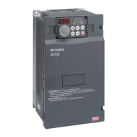
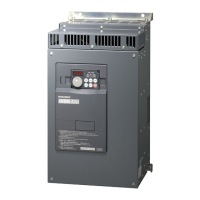
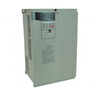
Provides outline dimension drawings for FR-A721/A741 inverters of 5.5K to 15K capacity.

7.3.2 Dedicated motor outline dimension drawings

Provides outline dimension drawings for SF-V5RU(H) motors (standard horizontal type) for various frame numbers.

7.4 Installation of the heatsink portion outside the enclosure for use

Advises on installing the heatsink portion outside the enclosure to reduce internal heat generation.

APPENDICES

Appendix 1 Main differences and compatibilities with the FR-A700 series

Summarizes the main differences and compatibilities between the FR-A700 and FR-A701 series inverters.

Appendix 2 Instructions for UL and cUL Compliance

Provides instructions for UL and cUL compliance regarding installation, wiring, and short circuit ratings.

Appendix 3 Control mode-based parameter (function) correspondence table and instruction code list

Provides a table mapping parameters to control modes and instruction codes for RS-485 communication.

Related product manuals