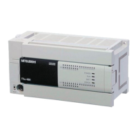
Do you have a question about the Mitsubishi Electric FX3S Series and is the answer not in the manual?
| Series | FX3S |
|---|---|
| Manufacturer | Mitsubishi Electric |
| Input Voltage | 100-240VAC or 24VDC |
| Power Supply | 100-240VAC or 24VDC |
| Type | PLC |
| Communication Ports | RS-422 |
| Operating Temperature | 0°C to +55°C |
| Output Type | Relay or Transistor |
Critical design considerations for safe PLC system operation and equipment protection.
Essential guidelines for safe and correct wiring to prevent hazards and damage.
Precautions for safe PLC startup, operation, and maintenance procedures.
Defines the required qualifications and training for personnel involved with the PLC.
Guidelines for using the product in general industries and special applications.
Explains the manual's format, structure, and referencing system for clarity.
Provides a general overview of the PLC's positioning control capabilities.
Displays block diagrams illustrating various unit combinations for positioning control.
Compares performance specifications of different products for positioning functionality.
Outlines the positioning modules, general outputs, and special adapters used for control.
Provides detailed specifications for PLC positioning functions and related hardware.
Covers essential information required before starting PLC programming for positioning.
Guides through testing the PLC's positioning instructions and operations.
Compares the DSZR and ZRN instructions for mechanical zero return.
Details the DSZR instruction for zero return using a DOG signal.
Explains the ZRN instruction for basic zero return operations.
Explains the instruction format, operands, and devices for the ABS instruction.
Explains how to read the absolute position data from a servo amplifier using the ABS instruction.
Outlines the methods for performing an initial zero return for absolute position systems.
Explains the two target position setting methods: incremental and absolute.
Details the DRVI instruction for performing 1-speed positioning using relative addresses.
Explains the DRVA instruction for 1-speed positioning using absolute addresses.
Explains the instruction format, operands, and devices for the DVIT instruction.
Describes the DVIT instruction for performing one-speed interrupt constant quantity feed.
Details the instruction format, operands, and devices for the PLSV instruction.
Explains the PLSV instruction for variable speed operation with rotation control.
Explains the instruction format, operands, and devices for the TBL instruction.
Describes the TBL instruction for batch data positioning operations.
Guides on setting built-in positioning parameters using GX Works2 or GX Developer.
Shows input/output assignments used in the example programs.
Provides an example program for forward/reverse rotation using relay ladder logic.
Demonstrates positioning using batch setting methods with GX Works2.
Explains how to interpret LED status for diagnosing PLC errors.
Guides on using GX Works2 to check and interpret PLC error codes.
Provides troubleshooting steps for cases where the servo or stepping motor fails to operate.
Offers solutions for troubleshooting issues where operation stops at an incorrect position.
Provides connection examples for MELSERVO-J4 series servo amplifiers.
Presents connection examples for MELSERVO-J3 series servo amplifiers.
Provides connection examples for MELSERVO-JN series servo amplifiers.
Offers connection examples for MELSERVO-J2 (-Super) series servo amplifiers.
Provides connection examples for MELSERVO-H series servo amplifiers.
Presents connection examples for MELSERVO-C series servo amplifiers.
Details the duration and scope of the gratis warranty for product defects.
Outlines repair terms after a product's production has been discontinued.
Lists the dates and revisions made to the manual content over time.





 Loading...