FX
3S
/FX
3G
/FX
3GC
/FX
3U
/FX
3UC
PLC User's Manual - Positioning Control Edition
Built-in Positioning Functions
2 Specifications
2.5 Output Specifications
B - 35
A
Common Items
B
Built-in
Positioning
Functions
Apx.
Example
Connection
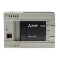
2.5.4 FX3U Series main unit (Transistor Output)
This section describes the transistor output specifications of the FX3U Series main unit. Please note that the
simultaneous turning-on rate is restricted for the output extension units and the main unit. For details on the
restriction, refer to the following manual.
Refer to the FX
3U Hardware Edition.
For MELSERVO Series amplifiers, use a sink input/sink output type PLC.
Pulse output terminals Y000, Y001, and Y002 are high-speed response output terminals.
To use the positioning instruction, adjust the load current of the NPN open collector to 10 to 100 mA (5 to 24 V DC)
.
Item Transistor output specifications
External voltage All outputs 5 to 30 V DC
Maximum load
Resistance load All outputs
The total load current of resistance loads per common termi-
nal should be the following value or less.
- 1 point output common:0.5 A
- 4 points output common:0.8 A
- 8 points output common:1.6 A
Inductive load All outputs
The total of inductive load per common terminal should be the
following value or less.
- 1 point output common:12 W/24 V DC
- 4 points output common:19.2 W/24 V DC
- 8 points output common:38.4 W/24 V DC
Open-circuit leakage current All outputs 0.1 mA or less at 30 V DC
ON voltage All outputs 1.5 V or less
Response time
OFFON
Y000 to Y002 5 s or less at 10 mA or more (5 to 24 V DC)
Y003 or more 0.2 ms or less at 200 mA (at 24 V DC)
ONOFF
Y000 to Y002 5 s or less at 10 mA or more (5 to 24 V DC)
Y003 or more 0.2 ms or less at 200 mA (at 24 V DC)
Circuit insulation All outputs Photocoupler insulation
Indication of output motion All outputs LED is lit when the photocoupler is driven.
Item Description
Operation voltage range 5 to 24 V DC
Operation current range 10 to 100 mA
Output frequency 100 kHz or less
Downloaded from ManualsNet.com search engine
 Loading...