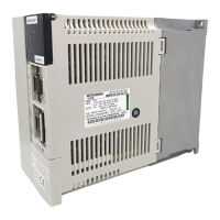
Do you have a question about the Mitsubishi Electric MELDAS MDS-R-V2-8080 and is the answer not in the manual?
| Type | CNC Controller |
|---|---|
| Series | MELDAS |
| Model | MDS-R-V2-8080 |
| Control Method | Digital Servo Control |
| Axis Control | 8 axes |
| Interpolation | Linear, Circular, Helical |
| Communication Interface | RS-232, Ethernet |
| Power Supply | 200-240 VAC |
| Operating Temperature | 0°C to 45°C |
| Storage Temperature | -20°C to 60°C |
Explanation of safety levels (DANGER, WARNING, CAUTION) and symbols for prohibited/mandatory matters.
Detailed safety precautions related to electric shock prevention, injury prevention, and fire prevention.
Detailed specifications for HF Series servomotors, including lists, torque characteristics, dimensions, and environmental conditions.
Specifications for MDS-R Series servo drive units (1-axis and 2-axis), covering installation conditions, lists, and outline dimensions.
Recommendations for selecting no-fuse breakers and contactors to ensure safe and proper installation for power supply units.
Wiring diagrams for connecting servomotors and detectors, covering various models and cable types.
Guidance on connecting the main circuit power supply, contactors, regenerative resistors, motor brakes, and emergency stops.
Details on wiring and controlling contactors, motor brakes, and external emergency stop signals for safe operation.
Essential parameters for system startup, covering basic specifications, electronic gears, detector types, and regenerative resistor settings.
Steps for adjusting current loop and speed loop gains to optimize servo control and machine stability.
Techniques for enhancing performance, including cutting precision, vibration suppression, overshooting, lost motion, and acceleration/deceleration.
Configuration of emergency stop functions, including deceleration control, dynamic braking, and vertical axis drop prevention.
Essential checks and troubleshooting steps to identify the cause of errors, warnings, or alarms.
Resolving startup issues by examining LED displays and ensuring correct unit settings and connections.
Comprehensive lists of alarms and warnings, including details on causes, investigation methods, stopping methods, and reset procedures.
Detailed guidance for resolving specific alarms and warnings, with investigation items and recommended remedies.
Criteria for selecting servomotor capacity based on load inertia ratio, short-time characteristics, and continuous characteristics.


