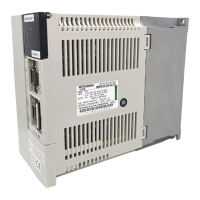
Do you have a question about the Mitsubishi Electric MELDAS MDS-R-V1-40 and is the answer not in the manual?
| Type | CNC Controller |
|---|---|
| Model/Series | MELDAS MDS-R-V1-40 |
| Spindle Control | Yes |
| Control Method | Digital Servo Control |
| Control Axis | 4 axes |
| Voltage | 200V AC |
| Power Supply | 3-phase |
| Communication Interface | RS-232 |
| Storage Environment | Temperature: -20-60°C, Humidity: 20-85% (non-condensing) |
Explains the severity levels of safety precautions and the meaning of warning symbols used in the manual.
Details precautions to avoid electric shock during installation, operation, and maintenance.
Outlines safety measures to prevent injuries related to linear servomotors and optical communication.
Lists precautions to prevent fires related to unit installation, wiring, and components.
Details precautions to prevent burns or injuries from hot parts and moving cooling fans.
Provides essential safety guidelines for transporting and installing units and motors.
Details essential precautions for correct and safe wiring of the servo system components.
Lists crucial steps and considerations for safe trial operation and parameter adjustment.
Covers safe practices for operating the system, including emergency stops and handling alarms.
Provides guidance on predicting hazardous situations and using appropriate safety mechanisms.
Guides on the physical installation of servomotors, including environmental conditions and vibration resistance.
Provides instructions for installing drive units, covering environmental conditions, clearances, and foreign matter prevention.
Covers adjusting current, speed, and position loop gains for optimal servo performance.
Explains how to configure emergency stop functions like deceleration control and drop prevention.
Presents the technical specifications for servomotors, including lists, characteristics, and dimensions.
Presents the technical specifications for servo drive units, including environment, lists, and dimensions.
Guides on selecting appropriate no-fuse breakers and contactors for power supply units.
Details connector pin assignments and signal names for main and control circuits.
Covers connecting servomotors and detectors, including specific series like HF.
Guides on connecting the main circuit power supply, including NFB and contactor installation.
Explains the wiring and control sequences for contactors used in the power supply circuit.
Covers wiring the motor brake control signal and its operational sequences.
Guides on wiring and setting up external emergency stop inputs for enhanced safety.
Covers initial settings for servo drive units, including rotary switch and LED display transitions.
Guides on setting initial parameters, including basic specifications and electronic gear parameters.
Provides a comprehensive list of servo parameters with their explanations and setting ranges.
Lists critical points to check and confirm before and during troubleshooting.
Provides guidance for troubleshooting startup issues based on LED displays and system errors.
Guides on troubleshooting specific alarms and warnings by identifying causes and remedies.
Outlines the three key elements for determining servomotor capacity: load inertia, short time, and continuous characteristics.
Provides a step-by-step example of selecting a servomotor, including load inertia and torque calculations.


