4 SYSTEM CONFIGURATION
4.5 Rules of System Configuration and Examples of Reconfiguration
79
4
4.5 Rules of System Configuration and Examples of
Reconfiguration
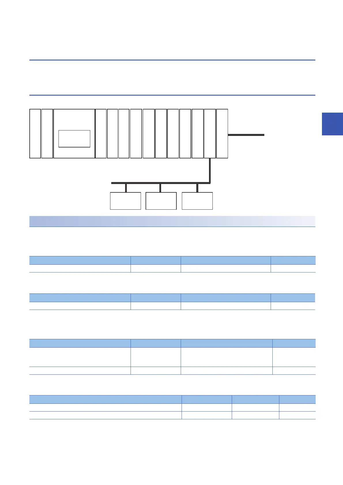
The rules of system configuration are explained below referring to a sample system configuration using an expansion board,
expansion adapter, I/O module, and intelligent function module.
System configuration example
The following system configuration is under consideration.
Check of limitation on the number of modules
Check if the sample system configuration is within the connectable-module range.
■Number of connected expansion boards
(Page 62 Number of connected expansion boards)
■Number of connected expansion adapters
(Page 62 Number of connected expansion adapters)
■Number of connected extension modules
• Number of modules connected on whole system
(Page 63 Overall system limitation)
• Number of modules connected to the CPU module
(Page 63 Connection to the CPU module)
Type No. of modules used Limitations Judgment
Expansion board 1 Only 1 OK
Type No. of modules used Limitations Judgment
Expansion adapter (Communication) 2 Up to 2 OK
Type No. of modules used Limitations Judgment
Extension module 11 Up to 16
(Extension power supply modules and connector
conversion module are excluded.)
OK
Bus conversion module 1 Only 1 OK
Type No. of modules used Limitations Judgment
Total No. of I/O modules, intelligent function modules, and bus conversion modules 11 Up to 12 OK
Total No. of intelligent function module and bus conversion modules 7 Up to 8 OK
FX5U-32MR/ES
FX5-16EYR/ES
FX5-16EYT/ES
FX5-16EX/ES
FX5-232ADP
FX5-232-BD
FX5-485ADP
FX5-CNV-BUS
FX5-40SSC-S
FX3U-1PG
FX3U-4AD
FX3U-128ASL-M
FX3U-4LC
FX3U-64CCL
CC-Link
FX5-16EYT/ES
To CC-Link
master station
The number of transmission points
setting for AnyWireASLINK
64 points
Remote I/O
station
Remote I/O
station
Remote I/O
station
 Loading...