EasyManua.ls Logo

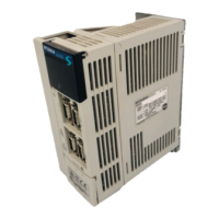
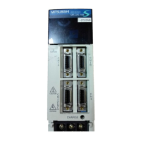
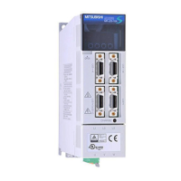
Mitsubishi Electric MR-J2S-20B User Manual

Mitsubishi Electric MR-J2S-20B
225 pages
To Next Page IconTo Next Page
Page #1 background imageLoading...
Page #1 background image
General-Purpose AC Servo
MODEL
MR-J2S- B
SERVO AMPLIFIER
INSTRUCTION MANUAL
SSCNET Compatible
J2-Super Series
F

Table of Contents

Other manuals for Mitsubishi Electric MR-J2S-20B

Questions and Answers:

Mitsubishi Electric MR-J2S-20B Specifications

General IconGeneral
ModelMR-J2S-20B
SeriesMR-J2S
CategoryAmplifier
TypeServo Amplifier
Rated Output200 W
Rated Output Current1.3 A
Feedback SystemIncremental encoder
Communication InterfaceRS-422
Input VoltageAC 200 V
Control MethodSine Wave PWM
Protection FunctionsOvercurrent, Overvoltage, Overload, Overheat
Operating Environment0 to 55 °C, 20 to 90% RH
Storage Environment-20 to 65 °C, 20 to 90% RH

Summary

Safety Instructions and Precautions

Understanding Warning and Caution Levels

Classifies safety instructions into WARNING and CAUTION levels for hazard communication.

Safety Precautions for Installation and Operation

Preventing Electric Shock Hazards

Details crucial safety measures to prevent electric shock during installation and operation.

Preventing Fire Hazards

Outlines precautions to prevent fire incidents related to servo amplifier and motor installation.

Preventing Personal Injury Risks

Provides safety guidelines to prevent injuries from electrical hazards and mechanical parts.

Installation, Handling, and Wiring Safety

Safe Transportation and Installation Practices

Covers safe practices for transporting and installing servo equipment, emphasizing load-bearing and clearances.

Wiring Safety and Equipment Usage

Details correct wiring procedures and safe equipment usage, including corrective actions for alarms.

Servo Amplifier Functions and Configuration

Detailed Servo Amplifier Specifications

Lists detailed technical specifications for various servo amplifier models, including power, environment, and structure.

Servo System Configuration with Auxiliary Equipment

Illustrates the wiring and connection of the servo system with auxiliary equipment for 3-phase power supplies.

Installation Guidelines and Environmental Requirements

General Installation Precautions and Safety

Highlights essential safety and installation guidelines, including stacking and environmental requirements.

Signals and Wiring Best Practices

Safety Warnings for Wiring Procedures

Emphasizes critical safety warnings and precautions for wiring servo amplifier and motor connections.

Control Signal System Connection Examples

Provides a detailed connection example for the control signal system of MR-J2S-700B or lower models.

I/O Signal Connector Pinout Configurations

Shows the pin configurations for CN1A, CN1B, CN2, and CN3 connectors on MR-J2S-700B or lower models.

Detailed I/O Signal and Connector Explanations

Explains the function and application of each connector and the details of I/O signals for servo amplifiers.

Understanding Alarm Occurrence and Timing Charts

Illustrates the sequence of events and timing during alarm occurrences in the servo system.

Servo Amplifier to Servo Motor Connection Procedures

Provides essential instructions for connecting the servo amplifier to the servo motor, including grounding procedures.

Electromagnetic Brake Circuit Configuration

Explains how to configure the electromagnetic brake circuit for activation by interface signals and forced stop.

Operation and Display Guide

Pre-Operation Checks Before Power-On

Lists essential checks for wiring, axis number, parameters, environment, and machine tightness before initial power-on.

Servo Amplifier Startup Procedures and Parameter Settings

Details the steps for powering on the servo amplifier and setting initial parameters for machine operation.

Test Operation Mode Functions

Describes how to perform jog and positioning operations using the MR Configurator software for testing.

Gain Adjustment Techniques

Overview of Gain Adjustment Methods

Explains different gain adjustment modes including auto tuning and manual modes for servo amplifier tuning.

Gain Tuning Using MR Configurator Software

Describes functions like machine analyzer, gain search, and machine simulation using MR Configurator software.

Auto Tuning Mode Functionality and Settings

Explains the operation and parameters for Auto Tuning Mode 1 and Mode 2 for automatic gain adjustment.

Manual Gain Adjustment (Mode 1) Procedures

Details the parameters used for simple manual gain adjustment, focusing on speed control.

Special Adjustment Functions for System Optimization

Adaptive Vibration Suppression Control

Describes the adaptive vibration suppression control's ability to detect and suppress mechanical resonance automatically.

Gain Changing Functionality and Applications

Outlines applications for changing servo gains during rotation, stop, or via external signals for stability.

Inspection and Troubleshooting Procedures

Periodic Inspection and Maintenance Procedures

Recommends periodic inspection checks for servo amplifiers, including cables and terminal blocks.

Troubleshooting Alarms and Warnings

Provides a comprehensive list of alarms and warnings with their display codes, names, and deactivation methods.

Alarm Remedies and General Handling Procedures

Outlines general procedures for handling alarms, including eliminating causes and resetting alarms.

Troubleshooting Warnings and Their Remedies

Lists remedies for common warnings such as battery issues, parameter errors, and forced stop signals.

Servo Amplifier Characteristics and Performance

Overload Protection Characteristics

Illustrates the electronic thermal relay protection curves for various servo amplifier models to prevent overload damage.

Dynamic Brake Characteristics and Time Constant

Describes the dynamic brake operation pattern and provides formulas and charts for calculating the time constant.

Options and Auxiliary Equipment

Regenerative Brake Options and Combinations

Details the combinations of servo amplifiers and regenerative brake options, including regenerative power ratings.

External Dynamic Brake Selection and Connection

Details the selection of external dynamic brakes and their connection diagrams for servo amplifiers.

MR Configurator Software for Servo Configuration

Lists the specifications and system requirements for the MR Configurator software used for servo configuration.

Absolute Position Detection System

Absolute Position Detection System Features

Explains the features and benefits of the absolute position detection system, enabling battery-backed position tracking.

Battery Installation Procedure for Absolute Position

Provides a step-by-step guide for safely installing the battery for the absolute position detection system, including static electricity precautions.

Related product manuals