Part 5: Review on Replacement of MR-J2S-30 kW or Higher Capacity Models with MR-J4-DU_
5 - 40
5.4.2 Parameter setting of brake units
Normally, it is unnecessary to change the FR-BU2-(H) parameters. The table below shows permission for
changing each parameter.
Parameter
Permission Remarks
Number Name
0 Brake mode switching NO Do not change the setting.
1 Monitor display data selection Available Refer to the "FR-BU2 installation guide".
2 Input terminal function selection 1 NO Do not change the setting.
3 Input terminal function selection 2
77 Parameter write selection
78
Cumulative energization time
carrying-over times
CLr Parameter clear
ECL Alarm history clear
C1 For manufacturer setting
5.4.3 Connection example
POINT
Connecting the PR terminal of a brake unit to the L+ terminal of a converter unit
will cause a malfunction to the brake unit. Make sure to connect the PR terminal
of a brake unit to that of a resistor unit.
(1) Use of the FR-BR-(H) resistor unit
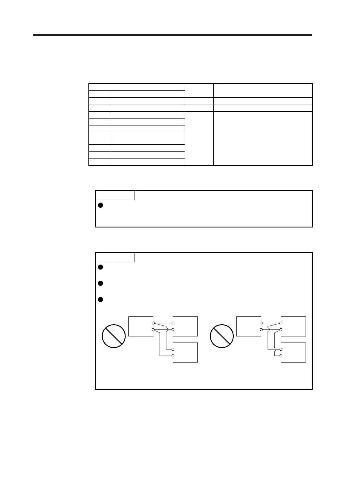
POINT
When connecting two brake units in parallel, use FR-BU2-(H) for both.
Otherwise an alarm or malfunction may occur.
Make sure to connect the master and slave terminals (MSG, SD) of one brake
unit to the master and the slave of the other respectively.
Do not connect as shown below.
N/-
P/+
Brake unit
Brake unit
Converter unit
L+
L-
N/-
P/+
Connecting multiple brake
units together to L+ and L-.
N/-
P/+
Brake unit
L+
L-
N/-
P/+
Brake unitConverter unit
Connecting multiple brake
units by daisy chain.
 Loading...