EasyManua.ls Logo

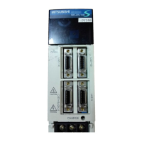
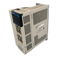
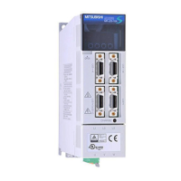
Mitsubishi Electric MR-J2S-*B Series User Manual

Mitsubishi Electric MR-J2S-*B Series
225 pages
To Next Page IconTo Next Page
Page #1 background imageLoading...
Page #1 background image
General-Purpose AC Servo
MODEL
MR-J2S- B
SERVO AMPLIFIER
INSTRUCTION MANUAL
SSCNET Compatible
J2-Super Series
F

Table of Contents

Questions and Answers:

Mitsubishi Electric MR-J2S-*B Series Specifications

General IconGeneral
Position ControlYes
Speed ControlYes
Torque ControlYes
SeriesMR-J2S-*B
TypeServo Amplifier
Input Power Supply3-phase 200-230V AC, 50/60Hz
Control MethodSine wave PWM control, current control system
CommunicationRS-422, RS-485
Feedback SystemIncremental encoder
Regenerative ResistorBuilt-in or external
Protection FunctionsOvercurrent, overvoltage, overload, encoder error, etc.
Power Supply3-phase 200-230V AC, 50/60Hz
Ambient Operating Temperature0 to 55°C
Storage Temperature-20 to 65°C

Summary

MELSERVO-J2-Super Series Instruction Manual

Safety Instructions

WARNING and CAUTION Levels

Explains the classification of safety instructions into WARNING and CAUTION levels.

Diagrammatic Symbols for Safety

Details the symbols used to indicate prohibited and mandatory actions for safety.

Preventing Electric Shock, Fire, and Injury

Preventing Electric Shock

Provides critical warnings and precautions to prevent electric shock during installation and operation.

Preventing Fire

Outlines cautions to prevent fire hazards related to installation and fault conditions.

Preventing Injury

Details precautions to prevent injury from electrical hazards, high temperatures, and rotating parts.

Additional Instructions for Installation

Transportation and Installation Precautions

Covers safe transportation and installation guidelines, including weight handling and environmental conditions.

Wiring and Connection Precautions

Details correct wiring procedures and warnings against incorrect connections for safe operation.

Test Run Adjustment and Usage Guidelines

Provides instructions for test run adjustments, general usage, and corrective actions for faults.

Maintenance, Inspection, and Waste Disposal

Covers periodic maintenance, inspection recommendations, and guidelines for product disposal.

Compliance with EC Directives

EC Directives Overview

Explains the purpose of EC directives and their applicability to servo amplifiers and motors.

Precautions for Compliance

Details precautions for servo amplifiers, motors, configuration, and environment to meet EC directives.

Conformance with UL/C-UL Standard

UL/C-UL Standard Compliance

Outlines requirements for servo amplifiers and motors to comply with UL/C-UL standards.

Installation and Safety Requirements

Covers installation, short circuit rating, capacitor discharge time, and wiring protection.

About the Manuals

1. Functions and Configuration

Introduction to MELSERVO-J2-Super Series

Provides an overview of the J2-Super series, its features, and advanced functions.

Function Block Diagram

Illustrates the functional blocks of the servo amplifier for different models.

Servo Amplifier Standard Specifications

Details the standard specifications for various servo amplifier models including environment and mass.

Function List

Lists and describes the various functions of the servo amplifier with reference fields.

Model Code Definition

Explains how to interpret the model code for servo amplifiers and their rating plates.

Servo Amplifier and Servo Motor Combinations

Provides a table showing compatible combinations of servo amplifiers and servo motors.

Servo Amplifier Structure and Parts Identification

Identifies key parts of the servo amplifier and describes their function and location.

Removal and Reinstallation of Front Cover

Provides step-by-step instructions for safely removing and reinstalling the servo amplifier's front cover.

Servo System with Auxiliary Equipment

Illustrates servo system configurations with auxiliary equipment and provides connection diagrams.

2. Installation

Environmental Conditions for Installation

Specifies the environmental conditions required for proper servo amplifier installation.

Installation Direction and Clearances

Details the correct installation direction and required clearances for servo amplifiers.

Keeping Out Foreign Materials

Provides guidelines to prevent foreign materials from entering the servo amplifier during installation.

Cable Stress Management

Offers advice on managing cable stress to prevent damage and ensure reliable connections.

3. Signals and Wiring

General Wiring and Signal Precautions

Includes essential warnings and cautions for safe and correct wiring practices.

Control Signal System Connection Examples

Shows connection examples for control signal systems for different servo amplifier models.

I/O Signals and Connector Arrangements

Details I/O signals, their connector pin configurations, and signal explanations.

Power Line Circuit Connection Examples

Illustrates connection examples for the power line circuit including NFB and MC.

Servo Amplifier Terminal Block Configuration

Describes the terminal arrangements and their functions for various servo amplifier capacities.

Power-on Sequence and Forced Stop

Explains the power-on sequence and the procedure for using the forced stop function.

Servo Amplifier and Servo Motor Connection

Provides instructions and diagrams for connecting the servo amplifier to the servo motor.

Servo Motor I/O Terminals

Details the I/O terminals for different servo motor series, including signal arrangements.

Servo Motor with Electromagnetic Brake

Explains the wiring and operation of the electromagnetic brake for servo motors.

Grounding Procedures

Covers essential grounding procedures for servo amplifiers and servo motors to prevent noise and shock.

Servo Amplifier Terminal Block Wiring Methods

Provides detailed methods for wiring the servo amplifier terminal blocks for different production dates.

Control Axis Selection

Explains how to set the control axis number using the axis select switch (SW1).

Power Line Circuit for MR-J2S-11KB to MR-J2S-22KB

Shows the power line circuit connection example for higher capacity servo amplifiers.

4. Operation and Display

Initial Power-on Checks

Lists checks to perform before initial power-on to ensure correct wiring and setup.

Startup Procedure and Parameter Setting

Guides through the startup process, including power-on, parameter setting, and servo-on.

Servo Amplifier Display Indications

Explains the servo amplifier display sequence and the meaning of various indications.

Test Operation Modes

Details various test operation modes like Jog, Positioning, Program, and Motor-less operations.

5. Parameters

Parameter Write Inhibit and Lists

Explains parameter write inhibit settings and provides a list of parameters and their functions.

Detailed Parameter Descriptions

Provides detailed explanations and initial values for various parameters (Basic, Adjustment, Expansion).

Analog Monitor Settings

Details how to set analog monitor outputs for servo status monitoring.

Modified Parameters for MR-J2S-B Series

Explains modifications and additions to parameters when replacing MR-J2 with MR-J2S series.

6. General Gain Adjustment

Gain Adjustment Methods on Single Servo Amplifier

Covers different gain adjustment methods like Auto Tuning and Manual modes.

Adjustment using MR Configurator Software

Explains gain adjustment functions using MR Configurator software (Machine Analyzer, Gain Search).

Auto Tuning Mode Operation and Procedures

Details the operation and adjustment procedures for Auto Tuning modes 1 and 2.

Response Level Setting in Auto Tuning

Guides on setting the response level for optimal performance and vibration-free operation.

Manual Mode 1 (Simple Manual Adjustment)

Provides instructions for simple manual gain adjustment for speed and position control.

Interpolation Mode for Multi-Axis Control

Explains the interpolation mode for matching position control gains across multiple axes.

Differences in Auto Tuning: J2 vs J2-Super

Compares auto tuning features between MELSERVO-J2 and J2-Super series.

7. Special Adjustment Functions

Function Block Diagram for Special Adjustments

Illustrates the signal flow for special adjustment functions like resonance suppression.

Machine Resonance Suppression Filter

Details the function and parameters of the machine resonance suppression filter.

Adaptive Vibration Suppression Control

Explains adaptive vibration suppression control for automatically suppressing mechanical system vibration.

Low-Pass Filter Function

Describes the low-pass filter function to prevent high-frequency resonance in mechanical systems.

Gain Changing Function

Covers the gain changing function for adjusting gains during rotation, stop, or via external signals.

Gain Changing Operation Examples

Provides examples of gain changing operations based on external input or droop pulses.

8. Inspection

Periodic Inspection Procedures

Recommends periodic checks for loose screws, cable damage, and general operating conditions.

Component Lifespan and Replacement

Lists components with limited lifespans and their replacement guidelines.

9. Troubleshooting

Alarms and Warning List

Lists all alarms and warnings with their display codes, names, and deactivation methods.

Remedies for Alarms

Provides detailed causes and actions for troubleshooting specific alarms.

Remedies for Warnings

Lists causes and actions for resolving warnings to ensure proper operation.

10. Outline Dimension Drawings

Servo Amplifier Dimensions

Provides outline dimensions and mounting information for various servo amplifier models.

Connector Dimensions and Types

Details the dimensions and types of connectors used for servo amplifiers and cables.

11. Characteristics

Overload Protection Characteristics

Illustrates electronic thermal relay protection curves for servo amplifiers and motors.

Power Supply Capacity and Generated Heat

Lists power supply capacities, generated heat, and area required for heat dissipation.

Dynamic Brake Characteristics

Explains dynamic brake operation and provides time constant charts for various servo motors.

Encoder Cable Flexing Life

Shows graphs illustrating the flexing life of encoder cables based on flexing radius.

Inrush Currents at Power-on

Indicates inrush currents for main and control circuits during power-on.

12. Options and Auxiliary Equipment

Regenerative Brake Options

Details combinations of servo amplifiers with regenerative brake options and their power ratings.

Brake Unit and Resistor Unit

Describes brake units and resistor units, including selection, connection, and dimensions.

Power Regeneration Converter

Explains the power regeneration converter, its selection, connection, and dimensions.

External Dynamic Brake

Covers the selection and connection of external dynamic brakes for servo motors.

Cables and Connectors

Lists various cables and connectors for servo amplifier and motor connections.

Maintenance Junction Card (MR-J2CN3TM)

Describes the maintenance junction card for connecting PCs and analog monitors simultaneously.

Battery (MR-BAT, A6BAT)

Details the battery used for the absolute position detection system and its handling precautions.

MR Configurator Software

Explains the specifications and system configuration for the MR Configurator software.

Power Regeneration Common Converter

Covers the selection, connection, and specifications of the power regeneration common converter.

Heat Sink Outside Mounting Attachment (MR-JACN)

Describes the heat sink attachment for dissipating servo amplifier heat outside the control box.

Recommended Wires

Provides recommendations for wire types and sizes for power supply and other wiring.

No-fuse Breakers, Fuses, Magnetic Contactors

Lists specifications for NFB, fuses, and magnetic contactors used with servo amplifiers.

Power Factor Improving DC Reactors

Details power factor improving DC reactors (FR-BAL) for power factor improvement.

Leakage Current Breaker

Explains selection methods for leakage current breakers to prevent malfunction due to leakage currents.

EMC Filter

Recommends EMC filters for compliance with EN standards and reducing noise.

13. Absolute Position Detection System

System Features and Operation

Describes the features of the absolute position detection system, including battery backup.

System Specifications

Lists the specifications for the electronic battery backup system, including battery life.

Battery Installation Procedure

Provides steps for installing the battery, including safety precautions.

Confirmation of Absolute Position Data

Explains how to confirm absolute position data using the MR Configurator software.

Related product manuals