EasyManua.ls Logo

Mitsubishi Electric Mr.Slim PKH-2FKA User Manual

Mitsubishi Electric Mr.Slim PKH-2FKA
86 pages
To Next Page IconTo Next Page
Page #1 background imageLoading...
Page #1 background image
TECHNICAL & SERVICE MANUAL
SPLIT-TYPE, HEAT PUMP AIR CONDITIONERS
CONTENTS
1. TECHNICAL CHANGES·······················2
2. PART NAMES AND FUNCTIONS········3
3. SPECIFICATIONS·································5
4. DATA···················································13
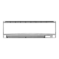
5. OUTLINES AND DIMENSIONS··········20
6. WIRING DIAGRAM·····························24
7.
REFRIGERANT SYSTEM DIAGRAM
······26
8. OPERATION FLOW-CHART··············28
9. MICROPROCESSOR CONTROL·······32
10. TROUBLESHOOTING························54
11. SYSTEM CONTROL ···························63
12. DISASSEMBLY PROCEDURE···········68
13. PARTS LIST········································71
14. OPTIONAL PARTS ·····························80
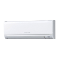
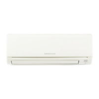
Indoor unit
[ Model names ] [ Service Ref. ]
PKH-2FKA PKH-2FKA
3
PKH-2.5FKA PKH-2.5FKA
2
PKH-2.5FKA
3
PKH-3FKA PKH-3FKA
2
PKH-3FKA
3
PKH-4FKSA PKH-4FKSA
2
PKH-4FKSA
3
No. OC132
REVISED EDITION-A
2001
Indoor unit
Wall Mounted
Series PKH
FILTER
CHECK MODE
CHECK
TEST RUN
REMOTE CONTROLLER
• PKH-2.5FKA
3
, PKH-3FKA
3
and
PKH-4FKSA
3
are added in
REVISED EDITION-A.
• Please void OC132 .
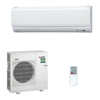
• This manual does not cover
outdoor units. When servicing
them, please refer to the service
manual No.OC128 REVISED
EDITION-C and this manual in
a set.
[Service Ref.]
PUH-2VKA
2, PUH-2VKA3,
PUH-2NKA1, PUH-2NKA2,
PUH-2.5VKA2, PUH-2.5VKA3,
PUH-2.5NKA1, PUH-2.5NKA2,
PUH-3VKA2, PUH-3VKA3,
PUH-3YKA2, PUH-3YKA3,
PUH-3YKA4,
PUH-3NKA1, PUH-3NKA2,
PUH-4YKSA3, PUH-4YKSA4,
PUH-4TKSA1
OC132--1.qxp 1.11.8 10:42 AM Page 1

Questions and Answers:

Mitsubishi Electric Mr.Slim PKH-2FKA Specifications

General IconGeneral
CategoryAir Conditioner
Power Supply220-240 V, 50 Hz
RefrigerantR32
Indoor Unit Weight9 kg
ModelPKH-2FKA
Energy Efficiency Ratio (Cooling)3.5

Summary

TECHNICAL & SERVICE MANUAL

Series PKH Wall Mounted

Overview of the PKH series wall-mounted air conditioners.

2 PART NAMES AND FUNCTIONS

3 SPECIFICATIONS

Indoor Unit Specifications (PKH-2FKA3)

Detailed specifications for the PKH-2FKA3 indoor unit.

PKH-2.5FKA2, PKH-2.5FKA3

60Hz specifications for PKH-2.5FKA2/3 indoor units.

PKH-4FKSA2, PKH-4FKSA3

60Hz specifications for PKH-4FKSA2/3 indoor units.

Outdoor Unit Specifications (PUH-2VKA2/3)

Detailed specifications for the PUH-2VKA2/3 outdoor unit.

PUH-2.5VKA2, PUH-2.5VKA3

Technical specifications for PUH-2.5VKA2/3 outdoor units.

PUH-3VKA2, PUH-3VKA3 / PUH-3YKA2, PUH-3YKA3, PUH-3YKA4

Technical specifications for PUH-3VKA/YKA outdoor units.

PUH-4YKSA3, PUH-4YKSA4

Technical specifications for PUH-4YKSA3/4 outdoor units.

PUH-2NKA1, PUH-2NKA2

60Hz specifications for PUH-2NKA1/2 outdoor units.

PUH-2.5NKA1, PUH-2.5NKA2

60Hz specifications for PUH-2.5NKA1/2 outdoor units.

PUH-3NKA1, PUH-3NKA2

60Hz specifications for PUH-3NKA1/2 outdoor units.

PUH-4TKSA1

60Hz specifications for PUH-4TKSA1 outdoor unit.

4 DATA

1) COOLING CAPACITY 50Hz

Cooling capacity data for 50Hz operation at various conditions.

3) HEATING CAPACITY 50Hz

Heating capacity data for 50Hz operation at various conditions.

2) COOLING CAPACITY 60Hz

Cooling capacity data for 60Hz operation at various conditions.

4) HEATING CAPACITY 60Hz

Heating capacity data for 60Hz operation at various conditions.

2. PERFORMANCE CURVE

Cooling

Performance curves showing capacity and total input ratio for cooling.

Heating

Performance curves showing capacity and total input ratio for heating.

3. ELECTRICAL DATA 50Hz

3. ELECTRICAL DATA 60Hz

4. STANDARD OPERATION DATA 50Hz

4. STANDARD OPERATION DATA 60Hz

5 OUTLINES AND DIMENSIONS

2. REMOTE CONTROLLER

6 WIRING DIAGRAM

PKH-2FKA3

Wiring diagram for the PKH-2FKA3 model.

7 REFRIGERANT SYSTEM DIAGRAM

8 OPERATION FLOW-CHART

OPERATION FLOW-CHART

COOLING OPERATION

Flowchart for the cooling operation sequence.

HEATING OPERATION

Flowchart for the heating operation sequence.

DRY OPERATION

Flowchart for the dry operation sequence.

AUTOMATIC COOLING/HEATING OPERATION

9 MICROPROCESSOR CONTROL

MICROPROCESSOR CONTROL

2. INDOOR UNIT CONTROL

Details compressor and fan control during cooling.

2-2 DRY operation

Detailed control logic for the indoor unit during dry operation.

2-3 HEAT operation

Detailed control logic for the indoor unit during heat operation.

2-4 AUTO operation (Automatic COOL/HEAT change over operation)

Details the automatic switching between cool and heat modes.

(4) Detecting abnormalities in the outdoor unit

Describes detection of outdoor unit abnormalities in HEAT operation.

(6) Defrosting operation

Explains the defrosting operation sequence and conditions.

2-6 TIMER operation

2-7 Test run

2-8 Emergency operation

2-10 Dip switch and jumper connector functions

2-11 INDOOR FAN CONTROL

3. OUTDOOR UNIT CONTROL

3-5 Defrosting in HEAT mode

Details the defrosting process and conditions in HEAT mode.

3-3 Protective functions

Explains protective functions and their behavior.

3-6 Actuators

3-7 Service functions

10 TROUBLESHOOTING

1. TROUBLE IN TEST RUN

Troubleshoot issues encountered during test run.

2. SELF DIAGNOSTIC FUNCTION WITH REMOTE CONTROLLER

How malfunctions are displayed during operation.

2-2 How to use the self diagnostic function for service

Guide on using the self-diagnostic function for service.

TROUBLESHOOTING ACCORDING TO CHECK CODE

Common Malfunctions (EO, P1-P5)

Troubleshooting for signal, thermistor, drain sensor, and pump issues.

Protection and System Errors (P6-P8)

Troubleshooting for frost, system errors, and outdoor unit abnormalities.

3. SERVICE DATA INDICATION BY SWITCHES ON OUTDOOR CONTROLLER BOARD

3-4 Check code indication

4. TROUBLESHOOTING ACCORDING TO CHECK CODE

LED Indicators for Malfunctions (LD1-LD8)

Detailed troubleshooting for each LED malfunction code.

5. WHEN OUTDOOR UNIT DOES NOT WORK

6. WRONG WIRING ON SITE

6-2 Phenomena due to wrong wiring between indoor and outdoor units

Lists phenomena caused by incorrect indoor/outdoor unit wiring.

7. OTHER TROUBLES AND CAUSES

9. How to check the parts

11 SYSTEM CONTROL

SYSTEM CONTROL

2. GROUP CONTROL WITH A SINGLE REMOTE CONTROLLER

How to wire and set up group control with one remote.

3. REMOTE ON-OFF AND INDIVIDUAL REMOTE CONTROLS

4. INDIVIDUAL CONTROL BY GROUPING THE REMOTE CONTROLLERS

5. MULTIPLE REMOTE CONTROL DISPLAY

6. AUTO RESTART FUNCTION

12 DISASSEMBLY PROCEDURE

PKH-3FKA2, PKH-3FKA3

Disassembly steps for PKH-3FKA2/3 indoor units.

DISASSEMBLY PROCEDURE

13 PARTS LIST

PARTS LIST

ELECTRICAL PARTS PKH-2FKA PKH-2FKA1 PKH-2FKA2 PKH-2FKA3

ELECTRICAL PARTS

5. CENTRALIZED REMOTE CONTROLLER

CENTRALIZED REMOTE CONTROLLER

Related product manuals