EasyManua.ls Logo

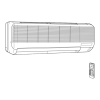
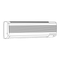
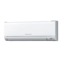
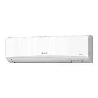
Mitsubishi Electric MS-18NN Series User Manual

Mitsubishi Electric MS-18NN Series
40 pages
To Next Page IconTo Next Page
Page #1 background imageLoading...
Page #1 background image
SERVICE MANUAL
SPLIT-TYPE, AIR CONDITIONERS
CONTENTS
1. TECHNICAL CHANGES ····································2
2. PART NAMES AND FUNCTIONS······················3
3. SPECIFICATION·················································5
4. OUTLINES AND DIMENSIONS ·························7
5. WIRING DIAGRAM ············································8
6. REFRIGERANT SYSTEM DIAGRAM··············10
7. PERFORMANCE CURVES······························13
8. MICROPROCESSOR CONTROL ····················15
9. SERVICE FUNCTIONS ····································23
10. TROUBLESHOOTING······································24
11. DISASSEMBLY INSTRUCTIONS·····················30
12. PARTS LIST······················································34
13. OPTIONAL PARTS···········································38
Wireless type
Models
No. OB188
MS-18NN -
(
WH
)
· MU-18NN -
MS-24NN -
(
WH
)
· MU-24NN -
S1S1
S1S1
OB188--1.qxp 25/9/97 6:06 PM Page 3

Questions and Answers:

Mitsubishi Electric MS-18NN Series Specifications

General IconGeneral
RefrigerantR410A
Indoor Unit Dimensions (W x H x D)Varies by model. Consult specific model documentation.
Outdoor Unit Dimensions (W x H x D)Varies by model. Consult specific model documentation.
TypeSplit System
Weight (Indoor Unit)9.5 kg
Weight (Outdoor Unit)32 kg
Cooling Capacity (kW)1.8 kW
Heating Capacity (kW)2.0 kW
Indoor Unit Weight9.5 kg
Outdoor Unit Weight32 kg

Summary

Technical Changes

Specifications

Outlines and Dimensions

Wiring Diagram

Indoor Unit Wiring Diagram

Wiring diagram for the indoor unit, detailing internal connections.

Outdoor Unit Wiring Diagram

Wiring diagram for the outdoor unit, detailing internal connections.

Refrigerant System Diagram

Refrigerant System Diagram for MS-18NN / MU-18NN

Illustrates the refrigerant flow for the 18NN model indoor and outdoor units.

Refrigerant System Diagram for MS-24NN / MU-24NN

Illustrates the refrigerant flow for the 24NN model indoor and outdoor units.

Microprocessor Control

Timer Operation

Emergency and Test Operation

Service Functions

Troubleshooting

Troubleshooting Cautions and Procedures

Provides essential precautions and a general procedure for troubleshooting.

Troubleshooting Flowchart and Check Table

Flowchart and check table for diagnosing operational issues and symptoms.

Trouble Criterion of Main Parts

Lists resistance and voltage criteria for diagnosing main component faults.

Disassembly Instructions

Related product manuals