EasyManua.ls Logo

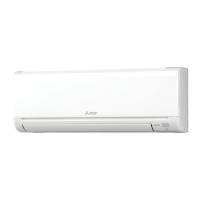
Mitsubishi Electric MSZ-GL09NA-U1 User Manual

Mitsubishi Electric MSZ-GL09NA-U1
54 pages
To Next Page IconTo Next Page
Page #1 background imageLoading...
Page #1 background image
Models
MSZ-GL06NA
-
U1
,
U2
MSY-GL09NA
-
U1
,
U2
MSZ-GL09NA
-
U1
,
U2
MSY-GL12NA
-
U1
,
U2
MSZ-GL12NA
-
U1
,
U2
MSY-GL15NA
-
U1
,
U2
MSZ-GL15NA
-
U1
,
U2
MSY-GL18NA
-
U1
MSZ-GL18NA
-
U1
MSY-GL24NA
-
U1
MSZ-GL24NA
-
U1
SERVICE MANUAL
CONTENTS
1. TECHNICAL CHANGES ······························2
2. PART NAMES AND FUNCTIONS ··················3
3. SPECIFICATION ········································6
4. OUTLINES AND DIMENSIONS ·····················8
5. WIRING DIAGRAM ···································10
6. REFRIGERANT SYSTEM DIAGRAM ···········12
7. SERVICE FUNCTIONS ······························13
8. MICROPROCESSOR CONTROL ·················15
9. TROUBLESHOOTING ······························· 23
10. DISASSEMBLY INSTRUCTIONS ················· 42
No. OBH732
REVISED EDITION-D
Outdoor unit service manual
MUZ-GLNA, MUY-GLNA Series (OBH733)
MXZ-CNA, MXZ-CNAHZ Series (OCH573)
PARTS CATALOG (OBB732)
INDOOR UNIT
Revision D:
MSZ-GL06/09/12/15NA -
U2
and
MSY-GL09/12/15NA -
U2
have been
added.
OBH732 REVISED EDITION-C is void.
MSZ-GL18NA
MSY-GL18NA

Questions and Answers:

Mitsubishi Electric MSZ-GL09NA-U1 Specifications

General IconGeneral
Cooling Capacity9, 000 BTU
SEER21.0
EER12.5
HSPF10.0
RefrigerantR-410A
Operating Temperature (Cooling)14°F to 115°F
TypeMini-Split
Heating Capacity10, 000 BTU
Voltage208/230V
Noise Level (Indoor)19 dB(A)
Power SupplySingle Phase

Summary

Service Manual Contents

Troubleshooting Guide

Provides guidance for diagnosing and resolving issues.

Refrigerant Handling and Safety Precautions

Refrigerant Usage Warning

Warns against using non-specified refrigerants and potential hazards.

Preparation for Service

Outlines necessary steps before starting repair work.

Precautions During Service

Lists safety measures to follow while performing repairs.

System Warnings

Critical warnings related to refrigeration circuit and compressor safety.

Service Functions Overview

Service Functions Details

Auto Restart Function

Explains the auto restart feature and how to disable it.

Unit Operation Modes

COOL Operation Mode

Details the COOL mode, including frost prevention.

DRY Operation Mode

Details the DRY mode, including frost prevention.

HEAT Operation Mode (MSZ)

Details the HEAT mode, including cold air prevention.

I FEEL CONTROL Operation (MSY)

Describes the "I FEEL CONTROL" mode for temperature sensing.

Operation Modes Details

I FEEL CONTROL Initial Settings

Defines how initial set temperature is decided in I FEEL CONTROL.

AUTO CHANGE OVER Operation (MSZ)

Details automatic switching between COOL and HEAT modes.

Horizontal Vane Operation

ECONO COOL Operation

Energy saving mode with temperature and vane adjustments.

POWERFUL Operation (GL24NA)

High-performance mode for specific models.

Vertical Vane Operation

Timer Operation

Timer Operation Details

SMART SET Operation

How to set and save preferred operation settings.

Special Operation Modes

Emergency and Test Operation

How to use the emergency operation switch for testing or emergencies.

Troubleshooting Cautions

Cautions Before Troubleshooting

Initial checks before starting troubleshooting procedures.

Servicing Precautions

Safety and handling precautions during servicing.

Troubleshooting Procedure

Step-by-step guide for diagnosing issues.

Troubleshooting - Failure Mode Recall

Failure Mode Recall Function Outline

Overview of the function to recall past errors.

Failure Mode Recall Flowchart

Step-by-step guide for using the failure mode recall function.

Releasing Failure Mode Recall Function

Procedures to exit the failure mode recall function.

Deleting Memorized Abnormal Conditions

Steps to clear stored error data.

Troubleshooting - Indoor Unit Failures

Indoor Unit Failure Table

Table detailing indoor unit failure modes, conditions, and remedies.

Troubleshooting Flowcharts

General Troubleshooting Flowchart

A general decision tree for diagnosing unit issues.

Specific Component Checks

Guides for checking specific components like thermistors or wiring.

Troubleshooting Check Table

Operation Indicator Lamp Failure Table

Lists abnormalities indicated by the operation indicator lamp.

Troubleshooting Criteria for Main Parts

MXZ Type Operation Setting Issue

Troubleshooting for conflicting operation modes in MXZ systems.

Component Resistance Checks

Resistance values for key components like thermistors and motors.

Troubleshooting Flow - Indoor Fan Motor (GL06-18NA)

Indoor Fan Motor Diagnosis Steps

Detailed steps for diagnosing indoor fan motor issues.

Troubleshooting Flow - Indoor Fan Motor (GL24NA)

Indoor Fan Motor Diagnosis (GL24NA)

Specific diagnostic steps for the GL24NA fan motor.

Troubleshooting Remote Control and PCB Issues

Remote Controller Check

Steps to check if the remote controller is functioning correctly.

Indoor PCB and Fan Motor Checks (GL06-15NA)

Indoor Power PCB and Fan Motor Checks

Diagnostic steps for indoor power PCB and fan motor.

Vane Motor Coil Resistance Check

Measuring vane motor coil resistance.

Indoor PCB and Fan Motor Checks (GL18NA)

Indoor Power PCB and Fan Motor Checks (GL18NA)

Diagnostic steps for GL18NA indoor power PCB and fan motor.

Indoor PCB and Fan Motor Checks (GL24NA)

Indoor Control PCB and Fan Motor Checks (GL24NA)

Diagnostic steps for GL24NA indoor control PCB and fan motor.

Troubleshooting Wiring and Serial Signal Errors (GL06-15NA)

Power Supply and Wiring Checks

Verifying power supply voltage and wiring integrity.

Serial Signal Error Checks

Diagnosing serial signal errors between units.

Troubleshooting Wiring and Serial Signal Errors (GL18-24NA)

Power Supply and Wiring Checks (GL18-24NA)

Verifying power supply and wiring for GL18-24NA models.

Serial Signal Error Checks (GL18-24NA)

Diagnosing serial signal errors for GL18-24NA models.

Electromagnetic Noise Interference

Test Point Diagrams and Voltages (GL06-15NA)

Test Point Diagrams and Voltages (GL06-15NA U2)

Test Point Diagrams and Voltages (GL18NA)

Test Point Diagrams and Voltages (GL24NA)

Disassembly Instructions - Panel Removal

Disassembly Instructions - PCB and Electrical Box Removal

Disassembly Instructions - Nozzle and Vane Motor Removal

Disassembly Instructions - Fan Motor, Coil Thermistor, Line Flow Fan Removal

Disassembly Instructions - Panel Removal (GL18NA)

Disassembly Instructions - PCB and Electrical Box Removal (GL18NA)

Disassembly Instructions - PCB and Vane Motor Removal (GL18NA)

Disassembly Instructions - Fan Motor, Coil Thermistor, Line Flow Fan Removal (GL18NA)

Disassembly Instructions - Panel, PCB, Electrical Box Removal (GL24NA)

Disassembly Instructions - Nozzle and Vane Motor Removal (GL24NA)

Disassembly Instructions - Fan Motor, Coil Thermistor, Line Flow Fan Removal (GL24NA)

Fixing the Indoor Coil Thermistor

Related product manuals