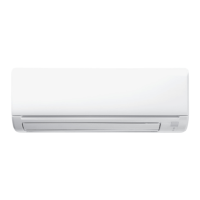
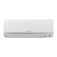
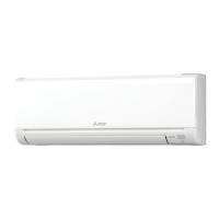
EasyManua.ls Logo

Mitsubishi Electric MSZ-GL12NA-U1 User Manual

Mitsubishi Electric MSZ-GL12NA-U1
54 pages
To Next Page IconTo Next Page
Page #1 background imageLoading...
Page #1 background image
Models
MSZ-GL06NA
-
U1
,
U2
MSY-GL09NA
-
U1
,
U2
MSZ-GL09NA
-
U1
,
U2
MSY-GL12NA
-
U1
,
U2
MSZ-GL12NA
-
U1
,
U2
MSY-GL15NA
-
U1
,
U2
MSZ-GL15NA
-
U1
,
U2
MSY-GL18NA
-
U1
MSZ-GL18NA
-
U1
MSY-GL24NA
-
U1
MSZ-GL24NA
-
U1
SERVICE MANUAL
CONTENTS
1. TECHNICAL CHANGES ······························2
2. PART NAMES AND FUNCTIONS ··················3
3. SPECIFICATION ········································6
4. OUTLINES AND DIMENSIONS ·····················8
5. WIRING DIAGRAM ···································10
6. REFRIGERANT SYSTEM DIAGRAM ···········12
7. SERVICE FUNCTIONS ······························13
8. MICROPROCESSOR CONTROL ·················15
9. TROUBLESHOOTING ······························· 23
10. DISASSEMBLY INSTRUCTIONS ················· 42
No. OBH732
REVISED EDITION-D
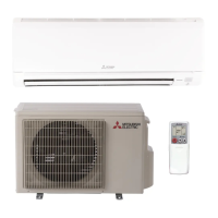
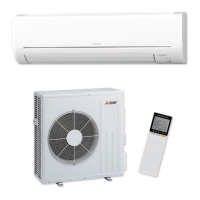
Outdoor unit service manual
MUZ-GLNA, MUY-GLNA Series (OBH733)
MXZ-CNA, MXZ-CNAHZ Series (OCH573)
PARTS CATALOG (OBB732)
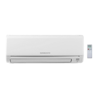
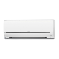
INDOOR UNIT
Revision D:
MSZ-GL06/09/12/15NA -
U2
and
MSY-GL09/12/15NA -
U2
have been
added.
OBH732 REVISED EDITION-C is void.
MSZ-GL18NA
MSY-GL18NA

Questions and Answers:

Mitsubishi Electric MSZ-GL12NA-U1 Specifications

General IconGeneral
Cooling Capacity12, 000 BTU/h
Heating Capacity12, 000 BTU/h
Heating Seasonal Performance Factor (HSPF)9.0
RefrigerantR410A
Indoor Unit Dimensions (W x H x D)29.1 x 11.8 x 7.5 inches
Outdoor Unit Dimensions (W x H x D)30.0 x 21.6 x 11.8 inches
Voltage208/230V
HSPF (Heating)9.0
Power Supply1-phase, 60Hz
EER (Cooling)11.7
Operating Temperature (Cooling)14°F to 115°F
Operating Temperature (Heating)75°F

Summary

Technical Changes

Specification

Wiring Diagram

Refrigerant System Diagram

Service Functions

Microprocessor Control

Emergency/Test Operation

Describes how to use the emergency operation switch for testing and servicing.

Troubleshooting

Cautions on Troubleshooting

Lists important safety and preliminary checks before troubleshooting.

Failure Mode Recall Function

Explains how to recall and interpret error codes indicated by the unit.

Troubleshooting Check Table

Lists specific abnormal points, symptoms, conditions, and remedies based on indicator lamps.

Troubleshooting Flow

Step-by-step diagnostic flowcharts for specific component failures like fan motor.

Test Point Diagram and Voltage

Illustrates test points and expected voltages on P.C. boards for diagnostics.

Disassembly Instructions

Related product manuals