Do you have a question about the Mitsubishi Electric NZ2GF2B1-16D and is the answer not in the manual?
| Model | NZ2GF2B1-16D |
|---|---|
| Manufacturer | Mitsubishi Electric |
| Type | Control Unit |
| Number of Inputs | 16 |
| Input Type | Digital |
| Voltage Rating | 24 V DC |
| Connection Type | Terminal Block |
| Storage Temperature | -25°C to 75°C |
| Current Consumption | 100 mA |
| Operating Temperature | 0°C to 55°C |
Precautions related to module design and system configuration to prevent accidents.
Precautions for safely mounting and installing the module.
Precautions for correctly connecting wires to the module and preventing electrical hazards.
Precautions for safe startup, operation, and maintenance of the module.
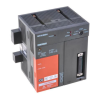
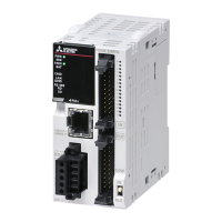
Details about the main I/O modules, including input and output types.
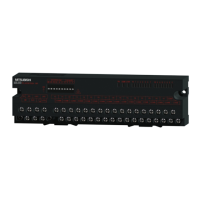
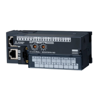
Details about extension I/O modules, including input and output types.
Describes how the I/O module exchanges signals with external devices and the master module.
Highlights key features of the I/O module, such as flexible configuration and easy settings.
Lists general operating conditions, resistance, and environmental specifications for the I/O module.
Detailed specifications for main I/O modules, including input and output types.
Detailed specifications for extension I/O modules, including input and output types.
Explains how to calculate the total current consumption of modules, including main and extension units.
Describes how to set the station number for an I/O module using the rotary switch.
Details the procedures for mounting modules on a DIN rail and connecting extension modules.
Covers wiring procedures for module power supply, FG, Ethernet cables, and external devices using terminal blocks.
Explains how to set module parameters and create programs using the engineering tool.
Explains how to set the station number for an I/O module using the rotary switch.
Covers crucial aspects of the installation environment and positioning for proper module operation.
Provides a step-by-step guide for connecting extension modules to the main module.
Explains how to set module parameters using the master station's CPU module.
Describes procedures for changing module parameters, including network configuration and slave station parameters.
Explains how the I/O module mode shifts at power-on (Unit test, Normal, Synchronous).
How the I/O module notifies the master station of errors or warnings using remote registers.
Allows setting response time to prevent incorrect inputs caused by noise.
Counts the total number of output ON times for each output point, even when the module is powered off.
Controls output based on internal input status without master station communication for high-speed control.
Enables I/O operations synchronized with the master station's cycle for coordinated timing.
Key precautions to follow when creating CC-Link IE Field Network programs.
Provides a practical example of creating a program for system configuration and I/O control.
Methods for checking error and warning codes using slave station commands or remote registers.
Comprehensive list of error codes, their classifications, descriptions, and recommended actions.
Addresses specific issues where the module may not operate properly without explicit error codes.
Provides practical examples and solutions for common input and output circuit issues.
Details the assignment of remote I/O signals for master/local and I/O modules.
Details the assignment of remote registers for master/local modules.
Information regarding compliance with EMC and Low Voltage Directives.
Provides external dimension diagrams for the main and extension modules.