Do you have a question about the Mitsubishi Electric QD75MH1 and is the answer not in the manual?
| Brand | Mitsubishi Electric |
|---|---|
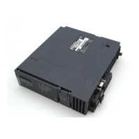
| Model | QD75MH1 |
| Category | Control Unit |
| Language | English |
Instructions for designing the positioning system, covering safety circuits, limit switches, and parameter settings.
Instructions for mounting the module, including base unit, fixing tabs, and screw tightening.
Instructions for wiring the module, including terminal layout, soldering, and cable routing.
Details all parameters for positioning control, including basic, detailed, OPR, and servo parameters.
Details the operation outline and methods for establishing the OP position and machine OPR completion.
Details setting requirements for various controls like linear, circular, and speed controls.
Covers speed limit, torque limit, software stroke limit, hardware stroke limit, and forced stop functions.
Explains errors and warnings detected by the QD75MH and how to confirm them.
Details error codes, names, descriptions, causes, and operation status at error occurrence.