EasyManua.ls Logo

Mitsubishi Electric PEAD-P3EA User Manual

Mitsubishi Electric PEAD-P3EA
52 pages
To Next Page IconTo Next Page
Page #1 background imageLoading...
Page #1 background image
TECHNICAL & SERVICE MANUAL
<indoor unit> Service ref.
Models
PEHD-P1.6EAH
PEHD-P2EAH
PEHD-P2.5EAH
PEHD-P3EAH
PEHD-P4EAH
PEHD-P5EAH
PEHD-P6EAH
PEAD-P1.6EA
PEAD-P2EA
PEAD-P2.5EA
PEAD-P3EA
PEAD-P4EA
PEAD-P5EA
PEAD-P6EA
TM
1. COMBINATION OF INDOOR AND
OUTDOOR UNITS ····································· 1
2. SAFETY PRECAUTION ···························· 2
3. PART NAMES AND FUNCTIONS ············· 4
4. SPECIFICATION ······································· 7
5. DATA ························································ 15
6. REFRIGERANT SYSTEM DIAGRAM ······ 36
7. OUTLINES & DIMENSIONS ···················· 37
8. WIRING DIAGRAM ·································· 39
9. DISASSEMBLY INSTRUCTIONS ············ 40
10
. PARTS LIST ············································· 42
11
. OPTIONAL PARTS ·································· 49
CONTENTS
INDOOR UNIT
REMOTE CONTROLLER
This manual does not cover the
following outdoor units. When
servicing them, please refer to
the service manual No.OC180
REVISED EDITION-A and this
manual as a set.
PUH-P1.6VGA PU-P1.6VGA
PUH-P1.6YGA PUH-P2VGA
PU-P2VGA PUH-P2YGA
PUH-P2.5VGA
1 PU-P2.5VGA1
PUH-P2.5YGA1
PUH-P3VGA PU-P3VGA
PUH-P3YGA PU-P3YGA
PUH-P4YGA PU-P4YGA
PUH-P5YGA PU-P5YGA
PUH-P6YGA PU-P6YGA
ON/OFF
TEMP.
Series PEHD
/
PEAD
R407C
2004
SPLIT-TYPE, HEAT PUMP
AIR CONDITIONERS
Question and Answer IconNeed help?

Do you have a question about the Mitsubishi Electric PEAD-P3EA and is the answer not in the manual?

Mitsubishi Electric PEAD-P3EA Specifications

General IconGeneral
BrandMitsubishi Electric
ModelPEAD-P3EA
CategoryAir Conditioner
LanguageEnglish

Summary

Introduction to the Service Manual

Manual Scope: PEHD/PEAD Series & R407C

Identifies manual's scope covering PEHD/PEAD Series with R407C refrigerant.

Technical & Service Manual Contents

Lists main sections covered in the technical and service manual.

Safety and Handling Procedures

R407C Refrigerant Handling Cautions

Details critical safety guidelines for R407C refrigerant use and system integrity.

Service Tools and Refrigerant Procedures

Lists essential tools and procedures for refrigerant recharging and repair services.

Indoor Unit Components

Indoor Unit Airflow Functionality

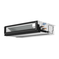
Explains the air intake and outlet functions of the indoor unit.

Remote Controller Interface

Remote Controller Button Functions

Identifies and describes the function of each button on the remote controller.

Remote Controller Display Icons

Explains the meaning of various symbols and indicators shown on the remote controller display.

Unit Specifications and Performance Data

Heat Pump Specs (ISO T1 Cooling/Heating)

Detailed specifications for cooling and heating performance under ISO T1 conditions.

Cooling Only Specs (ISO T1)

Detailed specifications for cooling-only models under ISO T1 rating conditions.

Cooling Capacity Adjustments

Correction Factors for Pipe Length

Tables showing cooling capacity adjustment factors based on refrigerant pipe length.

Heating Capacity Performance

Heating Capacity Data and Correction Graphs

Presents heating capacity and total input ratios influenced by outdoor/indoor conditions.

Fan Performance Curves

Fan Performance Curves: Static Pressure vs. Airflow

Graphs illustrating fan performance for various static pressure ranges and airflow.

Corrected Airflow Charts (Cooling & Heating)

Charts showing correction factors for airflow in cooling and heating modes.

Electrical Data

Heat Pump Electrical Data (ISO T1)

Electrical parameters for heat pump models under ISO T1 rating conditions.

Standard Operation Parameters

Heat Pump Operation Data (ISO T1)

Standard operating data including electrical, refrigerant, and temperature parameters.

Cooling Only Operation Data (ISO T1)

Standard operating data for cooling-only models under ISO T1 rating conditions.

Refrigerant System Overview

Indoor Unit Refrigerant Flow Diagram

Illustrates the refrigerant flow paths within the indoor unit for cooling and heating.

Unit Physical Dimensions

Indoor Unit Dimensions and Features

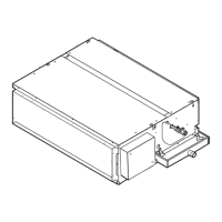
Provides detailed diagrams and dimensions for indoor units, including connection points and options.

Remote Controller Physical Dimensions

Remote Controller Views and Dimensions

Provides front, side, and rear views with dimensions for the remote controller unit.

Electrical Wiring Diagrams

Indoor/Outdoor Unit Wiring Schematics

Detailed wiring diagrams for indoor and outdoor units, including component labels and connections.

Disassembly Procedures

Fan Motor Removal

Step-by-step guide for safely removing the fan motor from the indoor unit.

Booster Heater Removal

Step-by-step instructions for removing the booster heater component.

Parts Identification

External Parts List

Lists external parts with part numbers, drawing numbers, and quantities for various models.

Blower Assembly Parts

Details parts related to the blower assembly, including fans, motors, and housings.

Control Box Components List

Lists components within the control box, such as terminal beds, PCBs, and relays.

Optional Accessories

Optional Refrigerant Pipe Kits

Lists optional refrigerant pipe kits available for different lengths and models.

Optional Motors and Drain Components

Details optional motors for extended duct runs and drain water lift-up mechanisms.

Related product manuals