EasyManua.ls Logo

Mitsubishi Electric PK18FK User Manual

Mitsubishi Electric PK18FK
80 pages
To Next Page IconTo Next Page
Page #1 background imageLoading...
Page #1 background image
TECHNICAL & SERVICE MANUAL
SPLIT-TYPE, AIR CONDITIONERS
CONTENTS
1. FEATURES ···········································2
2. SPECIFICATIONS·································5
3. DATA·····················································6
4. OUTLINES AND DIMENSIONS··········13
5.
REFRIGERANT SYSTEM DIAGRAM
······21
6. WIRING DIAGRAM·····························22
7. OPERATION FLOW-CHART··············26
8. MICROPROCESSOR CONTROL·······29
9. TROUBLESHOOTING························40
10. SYSTEM CONTROL···························48
11. DISASSEMBLY INSTRUCTIONS·······53
12. PARTS LIST········································60
13. OPTIONAL PARTS·····························74
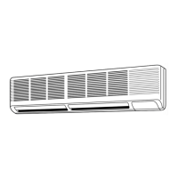
<Indoor unit> <Outdoor unit>
Models
Indoor unit
Wall Mounted
Series PK
MITSUBISHI ELECTRIC
ON
DRY
COOL
FAN
CHECK
SET TEMP
TIMER OFF
AUTO STOP
AUTO START
F
HR
F
LOW HIGH
AUTO RETURN
CHECK TEST RUN
POWER
ON/OFF
MODE SELECT
SET
TEMPERATURE
FAN COOL/DRY
COOLERWARMER
TIMER MODE HOURS
FAN SPEED LOW/HIOGH
AIR
DISCHARGE
UP/DOWN
SWING
STOP
CHECK TEST RUN
•CENTRALLY CONTROLLED•
REMOTE CONTROLLER
The Slim Line.
From Mitsubishi Electric.
PK12FK / PU12EK
PK18FK / PU18EK 1
PK24FK / PU24EK 1
PK30FK / PU30EK 1
PK36FK / PU36EK 1
No. OC121
L
I
S
T
E
D
R
OC121--1.qxp 24/6/97 2:11 AM Page 1
Questions and Answers:

Mitsubishi Electric PK18FK Specifications

General IconGeneral
BrandMitsubishi Electric
ModelPK18FK
CategoryAir Conditioner
LanguageEnglish

Summary

1. FEATURES

1. COMPACT DESIGN

Describes the compact size and installation flexibility.

2. A FURTHER REFINEMENT OF COMFORT WITH NOISE SUPPRESSION

Details improvements in quiet operation and airflow.

3. AUTO FLAP SHUTTER

Explains the function and operation of the auto flap shutter.

4. INSTALLATION : FAST AND ENDLESSLY ADAPTABLE

Covers aspects of installation flexibility and ease.

5. ADVANCED MICROPROCESSOR

(1) Easy to Use Microprocessor

Details the sophisticated control system and user-friendly interface.

(2) Non-polar Two-Wire Remote Controller Cables

Explains the benefits and specifications of the remote controller cabling.

(3) Automatic Cooling / Heating Changeover Operation

Describes the automatic mode switching for year-round comfort.

6. REDI-CHARGED REFRIGERANT SYSTEM

7. HIGH RELIABILITY AND EASY SERVICING

8. FOUR-WAY PIPING ACCESS MAKES INSTALLATION LAYOUT EASY

2 SPECIFICATIONS

3 DATA

Presents performance data, including cooling capacity and correction factors.

2. PERFORMANCE CURVE

PK12FK COOLING CAPACITY

Graph showing cooling capacity vs. outdoor temperature.

PK18FK COOLING CAPACITY

Graph showing cooling capacity vs. outdoor temperature.

3. STANDARD OPERATION DATA

4. OPERATING RANGE

Defines the operational limits for power supply and environmental conditions.

6. ADDITIONAL REFRIGERANT CHARGE (R-22 (OZ))

Provides guidelines for supplementary refrigerant charging.

4 OUTLINE AND DIMENSIONS

4.1. Indoor Unit PK12FK

Detailed dimensions and mounting information for the PK12FK indoor unit.

4.2. Outdoor Unit PU12EK 1

Technical drawings and dimensions for the PU12EK Outdoor Unit.

4.3. Remote controller

Diagram showing the dimensions and layout of the remote controller.

5 REFRIGRANT SYSTEM DIAGRAM

PK12/18/24FK

Illustrates the refrigerant flow for specific indoor/outdoor unit models.

6 WIRING DIAGRAM

6.1. Indoor Unit PK12FK

Shows the electrical connections for the PK12FK indoor unit.

6.2. Outdoor Unit PU12/18EK 1 WIRING DIAGRAM

Electrical wiring schematic for the PU12/18EK1 outdoor unit.

7 OPERATION FLOW-CHART

MAIN OPERATION

Outlines the primary operational logic and decision points of the unit.

COOLING OPERATION

Details the sequence of operations during cooling mode.

DRY OPERATION

Explains the operational logic and control flow for dry mode.

8 MICROPROCESSOR CONTROL

1.OUTLINE OF MICROPROCESSOR CONTROL

Explains the system architecture and component interactions.

2. COOLING OPERATION

Details the thermostat function and coil frost prevention.

3. DRY OPERATION

Describes thermostat and fan control logic for dry operation.

Remote control operation and Liquid Crystal Display

5. TEST RUN FUNCTION

6. EMERGENCY OPERATION

7. Dip switch and jumper connector functions

1 On remote controller board

Describes the function of dip switches on the remote controller.

2 On indoor controller board

Explains dip switch functions for indoor unit configuration.

8. OUTDOOR MICROPROCESSOR CONTROL

8-1 Protection function

Details protection mechanisms against various operational faults.

9 TROUBLESHOOTING

1.TROUBLE IN TEST RUN

Lists common issues encountered during test run and their causes.

2. SELF DIAGNOSTIC FUNCTION WITH REMOTE CONTROLLER

Explains how malfunctions are detected and displayed.

4. TROUBLESHOOTING ACCORDING TO CHECK CODE

6. WRONG WIRING ON SITE

7. OTHER TROUBLES AND CAUSES

10 SYSTEM CONTROL

1. VARIETY OF SYSTEM CONTROL FUNCTIONS

Describes different methods for controlling multiple units.

2. GROUP CONTROL WITH A SINGLE REMOTE CONTROLLER

Explains how to connect and configure multiple units for group control.

3. CONTROL USING TWO REMOTE CONTROLLERS : OPTIONAL REMOTE CONTROLLER (PAC-SK47RC)

4. REMOTE ON-OFF AND INDIVIDUAL REMOTE CONTROLS

6. MULTIPLE REMOTE CONTROL DISPLAY

11 DISASSEMBLY INSTRUCTIONS

1. Indoor unit PK24FK

Step-by-step guide for disassembling the PK24FK indoor unit.

2. Outdoor unit (PU18EK)

1. Electrical parts

Instructions for removing electrical components from the outdoor unit.

12 PARTS LIST

PK12FK STRUCTURAL PARTS

Lists structural components for the PK12FK indoor unit with part numbers.

PK18FK PK24FK ELECTRICAL PARTS PK30FK PK36FK

Lists electrical components for PK18/24/30/36FK models.

PU12EK/PU18EK1 STRUCTURAL PARTS

PU12EK/PU18EK1 FUNCTIONAL PARTS

PU24/30EK1 FUNCTIONAL PARTS

PU36EK1 FUNCTIONAL PARTS

13 OPTIONAL PARTS

1. REFRIGERANT PIPES

Details optional refrigerant piping kits for different models.

2. TIMER

Information on the programmable timer and its specifications.

4. MULTIPLE REMOTE CONTROLLER ADAPTER

5. CENTRALIZED REMOTE CONTROLLER

5-3 Connection method

Explains how to connect the centralized remote controller and power supply.

Related product manuals