Do you have a question about the Mitsubishi Electric PK30EK and is the answer not in the manual?
| Brand | Mitsubishi Electric |
|---|---|
| Model | PK30EK |
| Category | Air Conditioner |
| Language | English |
Details features of the Series PL Ceiling Cassettes, including installation and airflow.
Provides detailed specifications for PL18/24FK and PLL12/18/24FK models.
Presents cooling capacity data for various models under different conditions.
Details correction factors for cooling capacity based on refrigerant piping length.
Cooling capacity curves for PLL18FK, showing total capacity and power consumption.
Cooling capacity curves for PL18FK2, showing total capacity and power consumption.
Standard operation data for PLL12/18/24FK models.
Details power supply requirements and allowable voltage ranges.
Lists standard operating conditions like temperature and humidity.
Cooling capacity curves for PC24EK, showing total capacity and power consumption.
Cooling capacity curves for PC30EK, showing total capacity and power consumption.
Standard operation data for PC24/30/36/42EK and PCL24EK models.
Details power supply requirements and allowable voltage ranges.
Lists standard operating conditions like temperature and humidity.
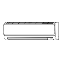
Cooling capacity curves for PKL12EK, showing total capacity and power consumption.
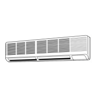
Cooling capacity curves for PK18EK, showing total capacity and power consumption.
Standard operation data for PKL12/18/24EK and PK18/24/30EK models.
Details power supply requirements and allowable voltage ranges.
Lists standard operating conditions like temperature and humidity.
Provides dimensions and outlines for PL18/24FK2 and PLL12/18/24FK indoor units.
Dimensions and outlines for PU18EK outdoor units.
Dimensions and outlines for PU24/30EK outdoor units.
Dimensions and outlines for PU36EK and PU42EK2 outdoor units.
Refrigerant system diagram for various indoor unit models.
Wiring diagram for PL18/24FK2 and PLL12/18/24FK indoor units.
Main operational flow-chart detailing the unit's startup and operational logic.
Overview of the microprocessor control system for indoor and remote units.
Describes how the unit judges frequency for auto vane control.
Explains auto vane operation during cooling mode, including discharge direction selection.
Details the LCD display and functions for PL/PLL series remote controllers.
Instructions on pre-test run checks for refrigerant leaks and power connections.
Step-by-step guide on how to perform a test run operation.
Explains DIP switch functions on the remote controller, including address and unit settings.
Details DIP switch functions on the indoor controller board for mode and operation settings.
Explains protection functions like phase error and high-pressure switch activation.
Describes how the outdoor coil thermistor controls unit operation and fan speed.
Explains how malfunctions are displayed on the remote controller LCD.
Guides on using the self-diagnostic function for service.
Describes issues with remote controller to indoor unit wiring.
Details phenomena resulting from incorrect indoor/outdoor unit wiring.
Explains how to control multiple units with one remote controller.
Describes controlling units with two remote controllers.
Details simultaneous ON/OFF and individual unit control.
Explains individual control by grouping remote controllers.
Describes controlling multiple units via a remote control display board.
Explains the auto restart function after power restoration.
Provides instructions on wiring for group control with a single remote controller.
Explains how to set unit addresses using SW2 for group control.
Describes unit control capabilities in group setup.
Details how to set SW17-7 for main/sub controller configuration.
Explains LCD indications on remote controllers for timer and self-diagnostic modes.
Illustrates the system setup for remote ON-OFF and individual controls.
Details wiring for the multiple remote control display adapter.
Describes the features and usage of the optional program timer.
Explains the purpose and connection of the timer adapter.
Explains how to locate and install the fresh air intake.
Details air flow and static pressure requirements for fresh air intake.
Describes sequential operation of the duct fan with the unit.
Step-by-step procedure for installing the branch duct.
Details the branch duct installation requirements and procedures.
Presents air flow and static pressure characteristics for branch ducts.
Provides steps for disassembling the PL24FK2 and PLL24FK indoor units.
Steps to remove drain pump, sensor, and indoor coil thermistor.
Steps to remove the unit panel.
Steps to remove the drain pan and terminal box.
Steps to remove the heat exchanger.
Steps to remove the drain pan.
Steps to remove the front panel assembly.
Steps to remove the louver motor.
Steps to remove the swing louver.
Steps to remove the fan motor.
Steps to remove the room temperature thermistor.
Steps to remove the indoor coil thermistor.
Steps to remove the right side plate.
Steps to remove the drain cover.
Steps to remove electrical parts from the unit.
Lists optional refrigerant pipes and their specifications.
Details the optional program timer and its part number.
Specifies the part number for the timer adapter.
Identifies the part number for the multiple remote controller adapter.
Lists the part number for the drain pump for PC/PCL series.
Lists part numbers for finish covers.
Lists part numbers for wind baffles.