EasyManua.ls Logo

Mitsubishi Electric PKA-A12LA1 User Manual

Mitsubishi Electric PKA-A12LA1
54 pages
To Next Page IconTo Next Page
Page #1 background imageLoading...
Page #1 background image
SERVICE MANUAL
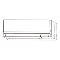
Indoor unit
[Model Name] [Service Ref.]
PKA-A12LA1
PKA-A12LA1
PKA-A18LA1
PKA-A18LA1
PARTS CATALOG (TCB117)
INDOOR UNIT
SPLIT-SYSTEM HEAT PUMP
No. TCH117
March 2023
CONTENTS
1. REFERENCE MANUAL ······················2
2. SAFETY PRECAUTION ······················2
3. PARTS NAMES AND FUNCTIONS ·······5
4. SPECIFICATIONS ······························6
5. NOISE CRITERION CURVES ···············7
6. OUTLINES AND DIMENSIONS ············8
7. WIRING DIAGRAM ···························· 9
8. REFRIGERANT SYSTEM DIAGRAM··· 10
9. TROUBLESHOOTING ······················ 11
10. FUNCTION SETTING ······················· 26
11. SPECIAL FUNCTION ······················· 27
12. DISASSEMBLY PROCEDURE ··········· 30
13. REMOTE CONTROLLER ·················· 34
WIRED REMOTE CONTROLLER
(Option)
WIRELESS REMOTE
CONTROLLER
(Option)
MENU
ON
OFF
RETURN
SELECT
HOLD
Questions and Answers:

Mitsubishi Electric PKA-A12LA1 Specifications

General IconGeneral
BrandMitsubishi Electric
ModelPKA-A12LA1
CategoryAir Conditioner
LanguageEnglish

Summary

REFERENCE MANUAL

OUTDOOR UNIT'S SERVICE MANUAL

Lists outdoor unit models, their service references, and catalog numbers for easy lookup.

SAFETY PRECAUTION

ALWAYS OBSERVE FOR SAFETY

Emphasizes disconnecting power before accessing terminals for safety.

CAUTIONS RELATED TO NEW REFRIGERANT

Highlights precautions for units using R410A refrigerant.

NOISE CRITERION CURVES

NOISE CRITERION CURVES

Displays noise level (dB) across various band center frequencies for performance analysis.

WIRING DIAGRAM

NOTES

Explains symbols, wiring, power supply, and copper wire usage in the diagram.

LEGEND

Lists symbols and their corresponding component names for diagram interpretation.

Self-diagnosis

Lists check codes and corresponding symptoms for self-diagnosis procedures.

TROUBLESHOOTING

TROUBLESHOOTING

Summarizes actions based on reoccurring or non-reoccurring troubles.

MALFUNCTION-DIAGNOSIS METHOD BY REMOTE CONTROLLER

Explains how to interpret self-diagnosis codes via remote controller for troubleshooting.

SELF-DIAGNOSIS ACTION TABLE

Details causes and countermeasures for specific self-diagnosis check codes.

TROUBLESHOOTING OF PROBLEMS

Provides troubleshooting steps for specific phenomena related to PCB and wiring issues.

EMERGENCY OPERATION

Explains how to operate the unit during remote controller failure or power issues.

HOW TO CHECK THE PARTS

Provides procedures for checking thermistors, vane motors, and fan motors.

DC Fan motor (fan motor/indoor controller circuit board)

Details the check method for the DC fan motor and circuit board.

TEST POINT DIAGRAM

Illustrates test points on the indoor controller board for diagnostics.

FUNCTIONS OF DIP SWITCH AND JUMPER WIRE

Explains the functions of DIP switches and jumper wires on the indoor controller board.

FUNCTION SETTING

UNIT FUNCTION SETTING BY THE REMOTE CONTROLLER

Explains how to set various unit functions using the remote controller.

Menu structure

Outlines the navigation path for setting various unit functions via the remote controller menu.

SPECIAL FUNCTION

ROTATION FUNCTION(AND BACK-UP FUNCTION, 2ND STAGE CUT-IN FUNCTION)

Describes alternating operation of main/sub units and 2nd stage cut-in for capacity.

BACK-UP HEATING FUNCTION

Explains the operation and setting of the back-up heating function.

DISASSEMBLY PROCEDURE

REMOVING THE PANEL

Step-by-step guide to removing the front panel and related parts.

REMOVING THE ELECTRICAL BOX

Instructions for removing the electrical box and its covers.

REMOVING THE NOZZLE ASSEMBLY (with VANE and VANE MOTOR) AND DRAIN HOSE

Procedure for removing the nozzle assembly, vane motor, and drain hose.

REMOVING THE INDOOR FAN MOTOR AND THE LINE FLOW FAN

Instructions for removing the indoor fan motor and line flow fan.

REMOVING THE PIPE TEMPERATURE THERMISTOR/LIQUID (TH2) AND COND./EVA. TEMP. THERMISTOR (TH5)

Steps to remove pipe temperature and condenser/evaporator thermistors.

REMOVING THE HEAT EXCHANGER

Guide to removing the heat exchanger assembly.

REMOVING THE ROOM TEMPERATURE THERMISTOR

Steps to remove the room temperature thermistor.

REMOTE CONTROLLER

REMOTE CONTROLLER FUNCTIONS

Explains the functions of the buttons and display elements of the remote controller.

Display

Details the icons and modes displayed on the remote controller screen.

Menu structure

Outlines the navigation path for settings via the remote controller menu.

ERROR INFORMATION

Guides users on how to check and reset error codes displayed on the remote controller.

SERVICE MENU

Explains how to access and use the service menu requiring a password.

TEST RUN

Details how to perform test runs for operation modes and vane settings.

PAR-SL101A-E Test Run Procedure

Specific steps to perform a test run using the PAR-SL101A-E remote controller.

FUNCTION SETTING

Instructions for setting unit functions and refrigerant addresses via the remote controller.

PAR-SL101A-E Function Setting Procedure

Steps to set unit functions using the PAR-SL101A-E remote controller.

ERROR HISTORY

Describes how to view and delete error logs from the remote controller.

SELF-DIAGNOSIS

Explains how to perform self-diagnosis and reset error history via remote controller.

PAR-SL101A-E Self-Diagnosis Procedure

Specific steps for self-diagnosis using the PAR-SL101A-E remote controller.

REMOTE CONTROLLER CHECK

Procedure to diagnose the remote controller's functionality and connection.

SMOOTH MAINTENANCE

Details how to set and view stable operation data for maintenance.

REQUEST CODE

Explains how to check operation data using request codes and refrigerant addresses.

Related product manuals