EasyManua.ls Logo

Mitsubishi Electric PLFY-P15VFM-E1 User Manual

Mitsubishi Electric PLFY-P15VFM-E1
30 pages
To Next Page IconTo Next Page
Page #1 background imageLoading...
Page #1 background image
TECHNICAL & SERVICE MANUAL
Indoor unit
[Model Name] [Service Ref.]
PLFY-P15VFM-E1.TH
PLFY-P20VFM-E1.TH
PLFY-P25VFM-E1.TH
PLFY-P32VFM-E1.TH
PLFY-P40VFM-E1.TH
PLFY-P50VFM-E1.TH
CONTENTS
1. SAFETY PRECAUTION
..........................
2
2. PARTS NAMES AND FUNCTIONS
........
4
3. SPECIFICATIONS
.................................
11
4. 4-WAY AIR FLOW SYSTEM
.................
13
5. OUTLINES AND DIMENSIONS
............
15
6. WIRING DIAGRAM
...............................
16
7.
REFRIGERANT SYSTEM DIAGRAM
......
17
8. TROUBLESHOOTING
..........................
18
9. DISASSEMBLY PROCEDURE
.............
26
PLFY-P15VFM-E1
PLFY-P20VFM-E1
PLFY-P25VFM-E1
PLFY-P32VFM-E1
PLFY-P40VFM-E1
PLFY-P50VFM-E1
Notes:
• This manual describes service data
of the indoor units only.
• RoHS compliant products have
<G> mark on spec name plate.
PARTS CATALOG (OCB617)
No. OCH617
March 2016
SPLIT-TYPE, HEAT PUMP AIR CONDITIONERS
R410A
INDOOR UNIT
Model name
indication
Question and Answer IconNeed help?

Do you have a question about the Mitsubishi Electric PLFY-P15VFM-E1 and is the answer not in the manual?

Mitsubishi Electric PLFY-P15VFM-E1 Specifications

General IconGeneral
BrandMitsubishi Electric
ModelPLFY-P15VFM-E1
CategoryAir Conditioner
LanguageEnglish

Summary

Mitsubishi Electric AC Service Manual

Refrigerant Safety and Handling

New Refrigerant Handling Precautions

Critical safety rules for using new refrigerants like R410A.

Service Cautions and Procedures

Guidelines for performing maintenance and service on the unit.

Refrigerant Charging Best Practices

Steps and advice for safe and effective refrigerant charging.

Essential R410A Service Tools

List of specialized tools required for R410A refrigerant system service.

Indoor Unit Component Identification

Indoor Unit Parts and Functions

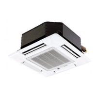
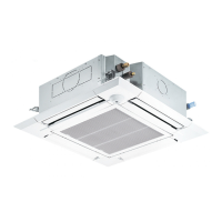
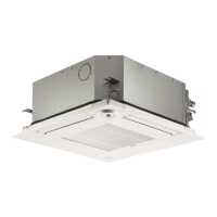
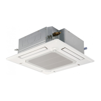
Detailed description of each component of the indoor unit and its role.

Wired Remote Controller Features

Overview of the wired remote controller's functions, buttons, and display interface.

Remote Controller Display Modes

Explanation of the Full and Basic display modes and common icons on the remote controller.

Indoor Unit Menu Navigation

Menu Settings and Display Options

Details on user-configurable settings available through the unit's menu system.

Service Menu Configuration Options

Settings available in the service menu for advanced configuration and diagnostics.

Wireless Remote Controller Guide

Technical Specifications

Indoor Unit Performance Specifications

Key performance metrics like cooling/heating capacity, airflow, and noise levels.

Electrical Parts Specifications

Detailed specifications for electrical components like motors, sensors, and terminals.

Airflow and Ducting System

Fresh Air Intake Installation Guidance

Instructions for properly installing the fresh air intake system.

Fresh Air Intake Performance Curves

Graphs showing static pressure characteristics related to fresh air intake amount.

Duct Fan Integration Procedures

How to connect and operate the indoor unit with an external duct fan.

Horizontal Vane Adjustment Method

Steps to fix the horizontal vane to a desired angle for airflow control.

Unit Dimensions and Layout

Wiring Diagram and Connections

Refrigerant System Diagram

Troubleshooting Common Errors

Test Run Error Code Solutions

A guide to error codes that appear during test runs and their corresponding solutions.

Component Testing Procedures

How to check the condition of various internal parts using electrical testers.

Thermistor Characteristic Graphs

Visual representation of thermistor resistance versus temperature.

Linear Expansion Valve Operation

Explanation of the linear expansion valve's function and connectivity.

Linear Expansion Valve Pulse Signals

How output pulse signals control the linear expansion valve's movement.

Linear Expansion Valve Fault Diagnosis

Troubleshooting steps for identifying and resolving issues with the linear expansion valve.

DC Fan Motor Troubleshooting

Methods for diagnosing problems with the DC fan motor and controller board.

DIP Switch Functionality Guide

Detailed explanation of the purpose and settings for each DIP switch.

SW21 Ceiling Height and Function Settings

Configuration of SW21 for ceiling height and general function selection.

SW22 Wireless Remote Pairing

How to set SW22 for pairing with wireless remote controllers.

SWE Drain Pump Test Function

Procedure for performing a drain pump test using the SWE connector.

Indoor Controller Board Test Points

Disassembly Procedures: External Parts

Air Intake Grille and Filter Removal

Step-by-step guide to removing the air intake grille and filter.

Indoor Unit Panel Removal Steps

Instructions for removing the unit's main panel and associated covers.

Accessing Electrical Components

How to open the control box and access internal electrical parts.

Room Temperature Thermistor Removal

Procedure for safely removing the room temperature thermistor (TH21).

Drain Pan Removal Guide

Steps for detaching and removing the unit's drain pan.

Pipe Temperature Thermistor Removal

Procedure for removing the pipe temperature thermistors (TH22, TH23).

Fan Motor and Turbo Fan Removal

Steps to remove the fan motor and turbo fan assembly.

Drain Pump and Float Switch Removal

Guide to removing the drain pump and its float switch.

Heat Exchanger Removal Procedure

Steps for safely removing the heat exchanger from the unit.

Related product manuals