Do you have a question about the Mitsubishi Electric PUHY-P400 and is the answer not in the manual?
| Brand | Mitsubishi Electric |
|---|---|
| Model | PUHY-P400 |
| Category | Air Conditioner |
| Language | English |
Explains symbols and manual retention for safety.
Provides warnings on installation, cable use, and seismic safety measures.
Details safety for electrical work, grounding, and handling the control box.
Highlights safety for refrigerant handling, leaks, and proper ventilation.
Discusses precautions for piping, materials, storage, and processing with R410A.
Lists required tools, vacuum pumps, and prohibited equipment for R410A.
Specifies using only R410A refrigerant and proper oil for handling.
Warns against installing in locations with gas leaks, unusual environments, or moisture.
Restricts unit usage to non-special purposes like food storage, animals, or plants.
Details safety for electrical work, including grounding, power supply, and breakers.
Advises on safe handling, transport, packing disposal, and protective gear.
Outlines preparation steps for test run, including power-on time and component checks.
Covers initial checks, safety, tools, and pipe verification before servicing.
Details piping materials, storage, processing, brazing, and air tightness testing.
Explains vacuum drying, refrigerant charging, leak remedies, and refrigerant characteristics.
Discusses refrigerating machine oil types and the impact of contaminants on the cycle.
Details compatible indoor unit combinations and high COP configurations.
Specifies cable types, maximum lengths, and wiring work requirements.
Explains switch settings and address configurations for controllers and units.
Illustrates typical system connections for MA, ME, and combined controllers.
Outlines restrictions on pipe length, including total length and height differences.
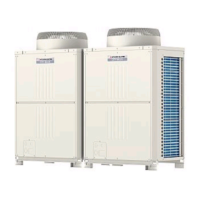
Details the external and internal components of the outdoor unit and its refrigerant circuit.
Explains the control box layout and the outdoor unit circuit board components.
Compares MA and ME remote controllers, detailing functions, specs, and selection criteria.
Guides on setting up group operations and interlocks for LOSSNAY units with controllers.
Details using built-in temperature sensors and setting temperature ranges for energy saving.
Provides electrical wiring diagrams for outdoor units of PUHY/EP models.
Explains the electrical wiring diagram for the transmission booster.
Details the external and internal components of the outdoor unit and its refrigerant circuit.
Describes the control box layout and the outdoor unit circuit board components.
Details the functions and factory settings of dipswitches on control boards and other components.
Describes the control logic for outdoor units, including operation modes and startup sequences.
Presents flowcharts for indoor and outdoor unit operations in cooling, heating, and dry modes.
Details pre-test run checks, execution methods, and normal operating symptoms.
Explains refrigerant characteristics, amount adjustment procedures, and modes.
Lists standard operating data and reference values for different models and operations.
Provides a comprehensive list of error codes, their definitions, and affected units.
Offers guidance on diagnosing and resolving errors displayed on the remote controller.
Guides on troubleshooting key components like sensors, valves, and fans.
Addresses troubleshooting for compressor issues, inverter problems, and wiring faults.
Explains how to interpret LED monitor displays for software versions, refrigerant types, and model capacities.
Details how to interpret LED monitor displays for software versions, refrigerant types, and model capacities.
Explains the interpretation of numerical and flag displays, including initial setting information.