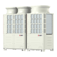
Do you have a question about the Mitsubishi Electric PUHY-P800 and is the answer not in the manual?
| Model | PUHY-P800 |
|---|---|
| Refrigerant | R410A |
| Maximum Height Difference (Outdoor to Indoor) | 50 m |
| Type | Outdoor Unit |
| Power Supply | 400V/3ph/50Hz |
General safety warnings and cautions for installation and use of the unit.
Precautions for handling R410A refrigerant, including piping and tool requirements.
Guidelines for unit installation location and environmental considerations.
Precautions for installation, moving, electrical work, and product handling.
Essential precautions to take before and during the test run operation.
Check refrigerant, symptoms, safety, tools, and verify connecting pipes before servicing.
List of essential tools and materials for installation and servicing, including R410A specific items.
Details on copper pipe types, thickness, processing, storage, and brazing requirements.
Procedures for air tightness testing, vacuum drying, and refrigerant charging.
Steps for refrigerant leak remedies and comparison of refrigerant characteristics.
Information on refrigerating machine oil for HFC systems and effects of contaminants.
Details compatible indoor units for standard and high COP combinations.
Information on M-NET transmission and remote controller cable types, sizes, and maximum lengths.
Guidance on setting switches and addresses for various units and controllers.
Examples of typical system connections for MA, ME, and combined remote controllers.
Sample control wiring for automatic address setup for systems with MA remote controllers.
Sample control wiring for systems with both MA and ME remote controllers.
Details pipe length restrictions for end branching and specific model series.
Identifies outdoor unit components and shows refrigerant circuit diagrams for various models.
Details the outdoor unit control box, including high-voltage warnings and internal boards.
Details the outdoor unit control board, M-NET board, INV board, and fan board.
Compares functions, specifications, and selection criteria for MA and ME remote controllers.
Instructions for group settings and LOSSNAY interlock settings using the ME remote controller.
Procedure for setting LOSSNAY interlocks using the MA remote controller.
Guidance on selecting the built-in or optional temperature sensor for remote controllers.
Detailed electrical wiring diagrams for the outdoor unit, covering various models.
Provides the complete electrical wiring diagram for the transmission booster.
Illustrates refrigerant circuit diagrams for different outdoor unit models.
Describes key outdoor unit components and their functions, including sensors and valves.
Details functions and factory settings of dipswitches on control boards and other units.
Explains control methods, startup sequences, initial control, and start-up control.
Provides flowcharts for indoor and outdoor unit mode determination and operation sequences.
Essential checks for refrigerant leaks, wiring, valves, power supply, and boosters before test run.
Step-by-step instructions for performing a test run using the MA remote controller.
Guidance on adjusting refrigerant based on symptoms and operating conditions.
Procedures for adding or extracting refrigerant using SW4-3 based on operation mode.
Identifies normal operational symptoms that may occur during or after operation.
Reference data for standard operation parameters during cooling and heating.
Comprehensive list of error codes, definitions, and related units for troubleshooting.
Guidance on interpreting remote controller error displays and taking corrective actions.
Methods for investigating transmission line issues, including wave shape and noise analysis.
Detailed troubleshooting steps for key components like sensors, valves, and motors.
Procedures for identifying and repairing refrigerant leaks in cooling and heating seasons.
Step-by-step instructions for removing and replacing the compressor.
Guidance on interpreting outdoor unit LED error displays and performing troubleshooting.
Guide on reading the LED monitor, including numerical values, flag displays, and initial settings.
Information on the unit's clock function and how time/date data is stored and displayed.
Table showing current data items displayed on the LED monitor, corresponding to SW1 settings.
Table showing various setting data items displayed on the LED monitor based on SW1 settings.


 Loading...